A
Note
-
Do
not
connect
to
an
outlet
at
this
point.
Note
-
In
a
building
block
configuration
with
connections
through
crossbar
boxes,
XBBOX#80
is
usually
the
master
XSCF,
and
XBBOX#81
is
the
standby
XSCF.
If
the
master
is
switched,
XBBOX#81
becomes
the
master
XSCF,
and
XBBOX#80
becomes
the
standby
XSCF.
Note
-
In
a
building
block
configuration
with
connections
through
crossbar
boxes,
no
serial
cable
is
connected
to
the
SPARC
M10-4S.
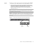
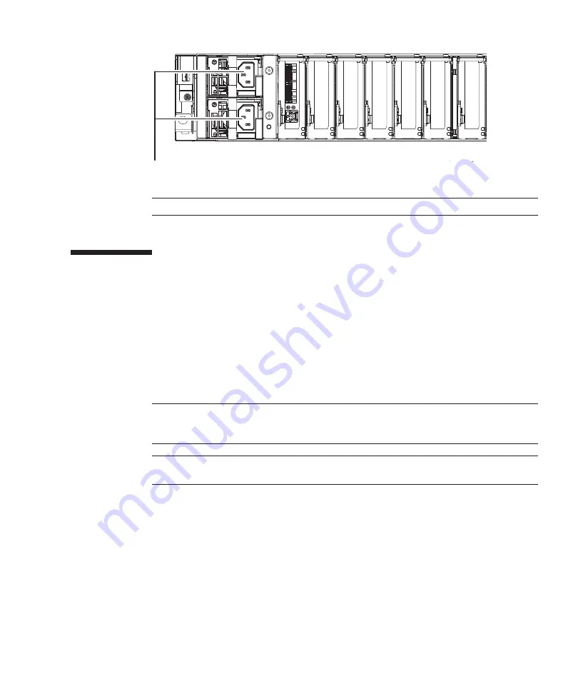
Figure
5-12
Power
supply
unit
locations
5.4
Connecting
Cables
to
a
Crossbar
Box
This
section
describes
the
procedure
for
connecting
the
serial
cable
to
a
crossbar
box.
1.
Connect
the
serial
cable
supplied
with
the
chassis
from
the
serial
port
of
the
XSCF
unit
(A
in
to
the
system
management
terminal.
In
a
building
block
configuration,
the
system
operates
with
batch
operations
by
the
chassis
of
the
master
XSCF.
Connect
the
serial
cable
to
the
master
XSCF.
Chapter
5
Connecting
Cables
to
the
Chassis
171
Summary of Contents for M10 Series
Page 1: ...Fujitsu M10 SPARC M10 Systems Installation Guide Manual Code C120 E678 12EN July 2015 ...
Page 10: ...Fujitsu M10 SPARC M10 Systems Installation Guide July 2015 x ...
Page 156: ...Fujitsu M10 SPARC M10 Systems Installation Guide July 2015 142 ...
Page 176: ...Fujitsu M10 SPARC M10 Systems Installation Guide July 2015 162 ...
Page 208: ...Fujitsu M10 SPARC M10 Systems Installation Guide July 2015 194 ...
Page 240: ...Fujitsu M10 SPARC M10 Systems Installation Guide July 2015 226 ...
Page 252: ...Fujitsu M10 SPARC M10 Systems Installation Guide July 2015 238 ...
Page 290: ...Fujitsu M10 SPARC M10 Systems Installation Guide July 2015 276 ...
Page 310: ...Fujitsu M10 SPARC M10 Systems Installation Guide July 2015 296 ...
Page 336: ...Fujitsu M10 SPARC M10 Systems Installation Guide July 2015 322 ...
Page 368: ...Fujitsu M10 SPARC M10 Systems Installation Guide July 2015 354 ...
Page 374: ...Fujitsu M10 SPARC M10 Systems Installation Guide July 2015 360 ...


