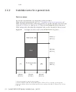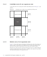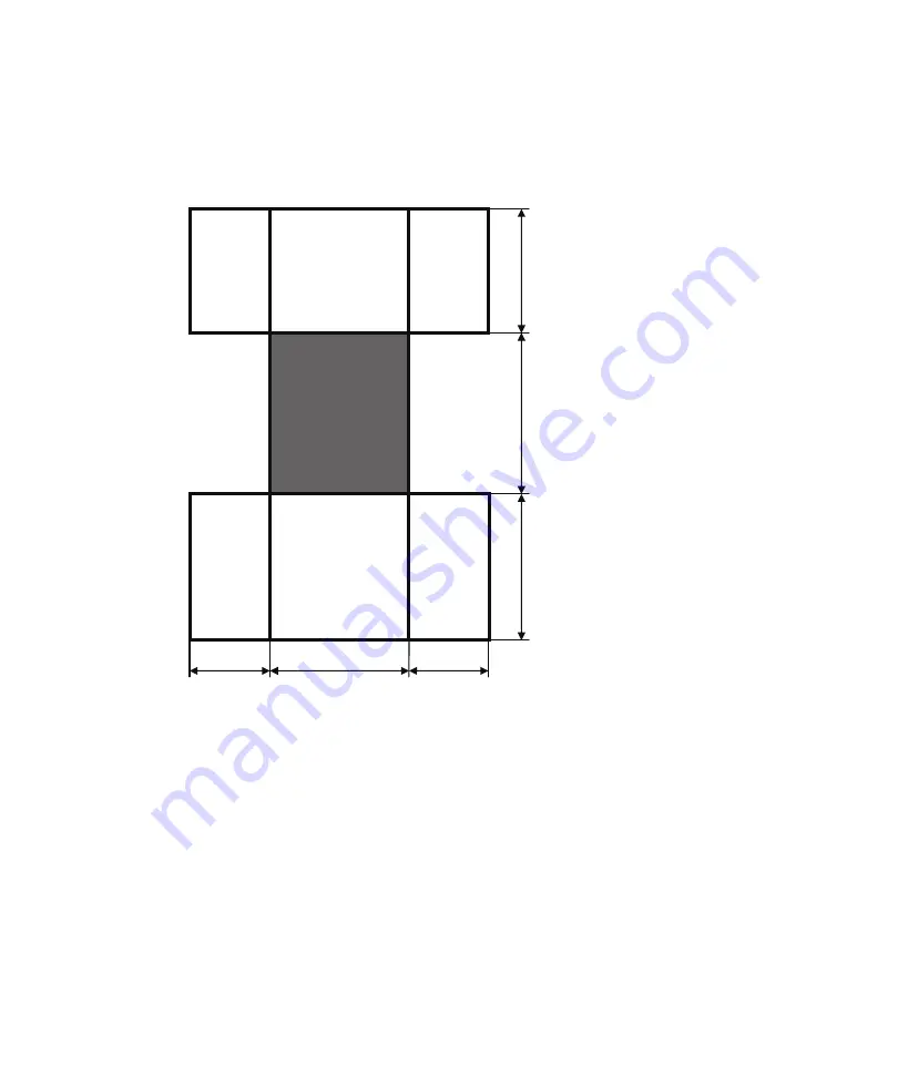
600 mm
(23.6 in.)
700 mm
(27.6 in.)
600 mm
(23.6 in.)
Rear service area
Front service area
Rack
900 mm
(35.4 in.)
1050 mm
(41.3 in.)
1200 mm
(47.2 in.)
2.4.4
Installation
area
for
an
expansion
rack
Confirm
that
the
service
areas
(space
used
for
maintenance)
shown
in
are
secured.
Figure
2-11
Example
of
service
areas
for
an
expansion
rack
(top
view)
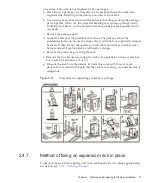
2.4.5
Bottom
view
of
an
expansion
rack
shows
the
locations
of
openings
for
taking
out/in
cables,
the
leveling
feet,
and
the
casters
on
the
bottom
of
the
expansion
rack.
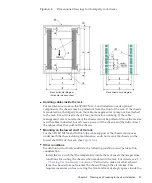
This
top-view
diagram
shows
the
bottom
of
the
inside
of
the
expansion
rack
as
viewed
from
directly
above.
Note
that
the
values
shown
are
expansion
unit
design
values.
To
fix
the
leveling
feet
to
the
floor,
determine
locations
allowing
for
a
tolerance
of
±2
mm
(±0.1
in.),
which
is
the
dimensional
tolerance
of
the
expansion
racks.
Fujitsu
M10/SPARC
M10
Systems
Installation
Guide
・
July
2015
34
Summary of Contents for M10 Series
Page 1: ...Fujitsu M10 SPARC M10 Systems Installation Guide Manual Code C120 E678 12EN July 2015 ...
Page 10: ...Fujitsu M10 SPARC M10 Systems Installation Guide July 2015 x ...
Page 156: ...Fujitsu M10 SPARC M10 Systems Installation Guide July 2015 142 ...
Page 176: ...Fujitsu M10 SPARC M10 Systems Installation Guide July 2015 162 ...
Page 208: ...Fujitsu M10 SPARC M10 Systems Installation Guide July 2015 194 ...
Page 240: ...Fujitsu M10 SPARC M10 Systems Installation Guide July 2015 226 ...
Page 252: ...Fujitsu M10 SPARC M10 Systems Installation Guide July 2015 238 ...
Page 290: ...Fujitsu M10 SPARC M10 Systems Installation Guide July 2015 276 ...
Page 310: ...Fujitsu M10 SPARC M10 Systems Installation Guide July 2015 296 ...
Page 336: ...Fujitsu M10 SPARC M10 Systems Installation Guide July 2015 322 ...
Page 368: ...Fujitsu M10 SPARC M10 Systems Installation Guide July 2015 354 ...
Page 374: ...Fujitsu M10 SPARC M10 Systems Installation Guide July 2015 360 ...

