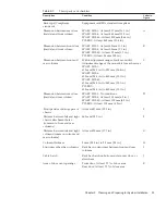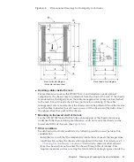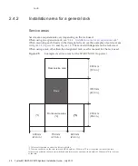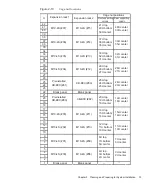
Table
2-5
Environmental
conditions
(continued)
Item
In
operation
Not
in
operation
Optimal
condition
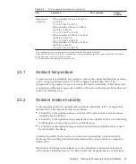
Temperature
conditions
-
When
installed
at
0
m
to
500
m
(0
ft.
to
1,640
ft.)
5˚C
to
35˚C
(41˚F
to
95˚F)
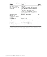
-
When
installed
at
500
m
to
1,000
m
(1,644
ft.
to
3,281
ft.)
5˚C
to
33˚C
(41˚F
to
91.4˚F)
-
When
installed
at
1,000
m
to
1,500
m
(3,284
ft.
to
4,921
ft.)
5˚C
to
31˚C
(41˚F
to
87.8˚F)
-
When
installed
at
1,500
m
to
3,000
m
(4,925
ft.
to
9,843
ft.)
5˚C
to
29˚C
(41˚F
to
84.2˚F)
*1
No
condensation
is
assumed
regardless
of
temperature
and
humidity
conditions.
*2
Only
the
SPARC
M10-1
and
the
PCI
expansion
unit
can
be
installed
in
an
office.
Install
the
SPARC
M10-4/M10-
4S
in
a
dedicated
room
such
as
a
server
room.
*3
All
the
altitudes
indicate
heights
above
sea
level.
2.5.1
Ambient
temperature
To
maintain
system
reliability
and
operator
comfort,
the
optimal
ambient
temperature
is
21°C
or
higher
but
less
than
23°C
(70°F
or
higher
but
less
than
74°F).
This
temperature
range
makes
it
easy
to
maintain
the
relative
humidity.
While
the
system
is
operating
within
this
range,
even
a
failure
of
the
air
conditioning
facilities
does
not
cause
it
to
suddenly
stop.
2.5.2
Ambient
relative
humidity
To
process
data
safely,
the
optimal
ambient
relative
humidity
is
45%
or
higher
but
less
than
50%.
The
reasons
for
this
are
as
follows:
■
A
humidity
in
the
optimum
range
can
protect
the
system
from
corrosion
issues
caused
by
high
humidity
■
A
humidity
in
the
optimum
range
means
that
even
a
failure
of
the
air
conditioning
facilities
does
not
cause
the
system
to
suddenly
stop
■
A
humidity
in
the
optimum
range
can
prevent
failures
and
malfunctions
caused
by
electrostatic
discharge
A
relative
humidity
that
is
too
low
is
conducive
to
generating
a
static
electricity
discharge.
The
resulting
intermittent
interference
may
cause
a
failure
or
temporary
malfunction.
Electrostatic
discharge
is
more
likely
to
occur
and
harder
to
eliminate
at
locations
with
a
relative
humidity
below
35%.
Electrostatic
discharge
becomes
a
critical
issue
Chapter
2
Planning
and
Preparing
for
System
Installation
39
Summary of Contents for M10 Series
Page 1: ...Fujitsu M10 SPARC M10 Systems Installation Guide Manual Code C120 E678 12EN July 2015 ...
Page 10: ...Fujitsu M10 SPARC M10 Systems Installation Guide July 2015 x ...
Page 156: ...Fujitsu M10 SPARC M10 Systems Installation Guide July 2015 142 ...
Page 176: ...Fujitsu M10 SPARC M10 Systems Installation Guide July 2015 162 ...
Page 208: ...Fujitsu M10 SPARC M10 Systems Installation Guide July 2015 194 ...
Page 240: ...Fujitsu M10 SPARC M10 Systems Installation Guide July 2015 226 ...
Page 252: ...Fujitsu M10 SPARC M10 Systems Installation Guide July 2015 238 ...
Page 290: ...Fujitsu M10 SPARC M10 Systems Installation Guide July 2015 276 ...
Page 310: ...Fujitsu M10 SPARC M10 Systems Installation Guide July 2015 296 ...
Page 336: ...Fujitsu M10 SPARC M10 Systems Installation Guide July 2015 322 ...
Page 368: ...Fujitsu M10 SPARC M10 Systems Installation Guide July 2015 354 ...
Page 374: ...Fujitsu M10 SPARC M10 Systems Installation Guide July 2015 360 ...

