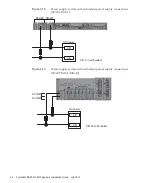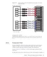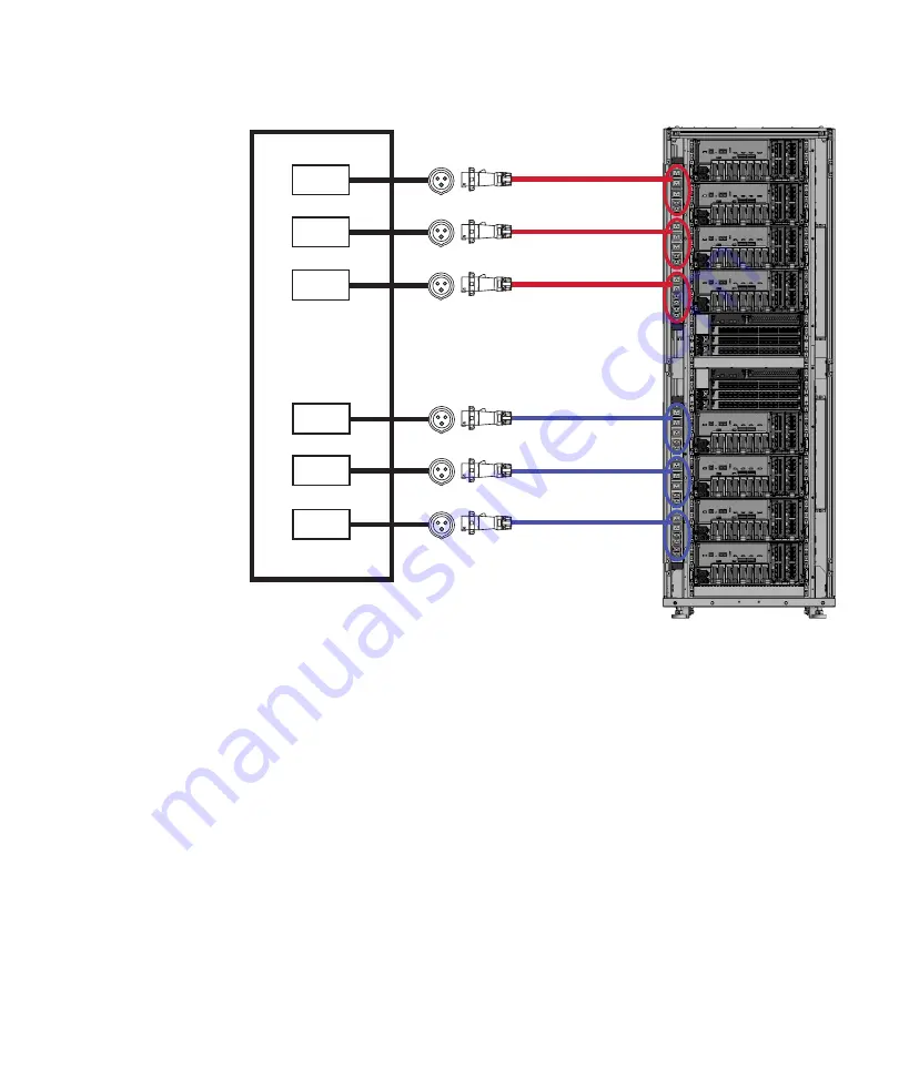
PDU#1 AC2
PDU#1 AC1
PDU#1 AC0
PDU#0 AC2
PDU#0 AC1
PDU#0 AC0
CB
CB
CB
CB
CB
CB
(*1)
(*3)
(*3)
(*3)
(*3)
(*3)
(*3)
(*2)
(*1)
(*2)
(*1)
(*2)
㪘㪚㩷㪧㫆㫎㪼㫉㪄㫊㫌㫇㫇㫃㫐㩷㪽㪸㪺㫀㫃㫀㫋㫀㪼㫊
㪜㫏㫇㪸㫅㫊㫀㫆㫅㩷㫉㪸㪺㫂
㪚㪙㪑㩷㪚㫀㫉㪺㫌㫀㫋㩷㪹㫉㪼㪸㫂㪼㫉
*1
For
expansion
rack
2,
use
PDU#3.
*2
For
expansion
rack
2,
use
PDU#2.
*3
Each
PDU
outlet
is
connected
to
the
power
cord
shown
in
the
figure.
The
system
consumes
no
power
when
there
is
no
device
connected
to
the
PDU
outlets.
For
the
wiring
of
power
cords
within
the
expansion
rack,
see
Figure
2-23
Power
supply
system
with
three-phase
power
feed
(expansion
rack:
single
power
feed)
Chapter
2
Planning
and
Preparing
for
System
Installation
49
Summary of Contents for M10 Series
Page 1: ...Fujitsu M10 SPARC M10 Systems Installation Guide Manual Code C120 E678 12EN July 2015 ...
Page 10: ...Fujitsu M10 SPARC M10 Systems Installation Guide July 2015 x ...
Page 156: ...Fujitsu M10 SPARC M10 Systems Installation Guide July 2015 142 ...
Page 176: ...Fujitsu M10 SPARC M10 Systems Installation Guide July 2015 162 ...
Page 208: ...Fujitsu M10 SPARC M10 Systems Installation Guide July 2015 194 ...
Page 240: ...Fujitsu M10 SPARC M10 Systems Installation Guide July 2015 226 ...
Page 252: ...Fujitsu M10 SPARC M10 Systems Installation Guide July 2015 238 ...
Page 290: ...Fujitsu M10 SPARC M10 Systems Installation Guide July 2015 276 ...
Page 310: ...Fujitsu M10 SPARC M10 Systems Installation Guide July 2015 296 ...
Page 336: ...Fujitsu M10 SPARC M10 Systems Installation Guide July 2015 322 ...
Page 368: ...Fujitsu M10 SPARC M10 Systems Installation Guide July 2015 354 ...
Page 374: ...Fujitsu M10 SPARC M10 Systems Installation Guide July 2015 360 ...


