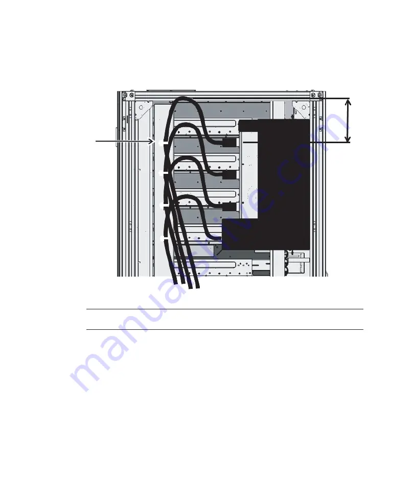
30cm (12 in.)
A
Remarks
-
shows
single-phase
power
feed.
The
required
lengths
are
the
same
as
for
three-phase
power
feed.
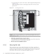
d.
Secure
all
the
power
cords
to
the
column,
with
the
supplied
binding
bands
(A
in
When
securing
them,
allow
an
extra
length
of
about
30
cm
(12
in.)
in
each
power
cord.
Figure
3-13
Securing
power
cords
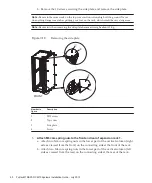
4.
Attach
the
side
plate
that
was
removed
in
step
2.
Attach
the
plate
by
reversing
the
removal
procedure
of
step
2.
Move
the
rack
as
appropriate
into
position
for
attaching
the
side
plate.
5.
Move
the
rack
to
the
installation
location.
3.3.2
Securing
the
rack
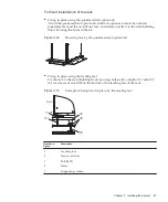
When
installing
the
rack,
always
adjust
the
leveling
feet
as
follows,
regardless
of
whether
the
rack
will
be
anchored
to
the
building
floor.
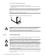
Keep
the
rack
level
with
the
leveling
feet.
Make
sure
that
the
casters
are
approximately
2
mm
(0.1
in.)
above
the
floor
surface.
The
casters
must
not
support
the
weight
of
the
rack.
Fujitsu
M10/SPARC
M10
Systems
Installation
Guide
・
July
2015
86
Summary of Contents for M10 Series
Page 1: ...Fujitsu M10 SPARC M10 Systems Installation Guide Manual Code C120 E678 12EN July 2015 ...
Page 10: ...Fujitsu M10 SPARC M10 Systems Installation Guide July 2015 x ...
Page 156: ...Fujitsu M10 SPARC M10 Systems Installation Guide July 2015 142 ...
Page 176: ...Fujitsu M10 SPARC M10 Systems Installation Guide July 2015 162 ...
Page 208: ...Fujitsu M10 SPARC M10 Systems Installation Guide July 2015 194 ...
Page 240: ...Fujitsu M10 SPARC M10 Systems Installation Guide July 2015 226 ...
Page 252: ...Fujitsu M10 SPARC M10 Systems Installation Guide July 2015 238 ...
Page 290: ...Fujitsu M10 SPARC M10 Systems Installation Guide July 2015 276 ...
Page 310: ...Fujitsu M10 SPARC M10 Systems Installation Guide July 2015 296 ...
Page 336: ...Fujitsu M10 SPARC M10 Systems Installation Guide July 2015 322 ...
Page 368: ...Fujitsu M10 SPARC M10 Systems Installation Guide July 2015 354 ...
Page 374: ...Fujitsu M10 SPARC M10 Systems Installation Guide July 2015 360 ...


