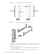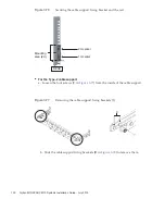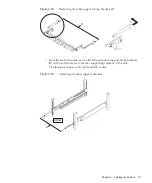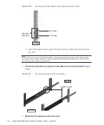
C
REAR
(M3 screws)
REAR
Circular
hole sections
D
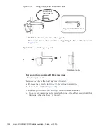
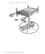
Figure
3-85
Attaching
the
cable
support
●
For
the
Type-2
cable
support
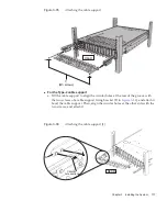
a.
Tilt
the
cable
support
to
align
the
circular
holes
at
the
rear
of
the
groove
with
the
two
screws
of
a
cable
support
fixing
bracket
(D
in
),
and
attach
it.
Level
the
cable
support.
Then,
align
the
circular
holes
at
the
other
side
with
the
two
screws,
and
attach
it.
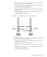
Figure
3-86
Attaching
the
cable
support
(1)
Chapter
3
Installing
the
System
137
Summary of Contents for M10 Series
Page 1: ...Fujitsu M10 SPARC M10 Systems Installation Guide Manual Code C120 E678 12EN July 2015 ...
Page 10: ...Fujitsu M10 SPARC M10 Systems Installation Guide July 2015 x ...
Page 156: ...Fujitsu M10 SPARC M10 Systems Installation Guide July 2015 142 ...
Page 176: ...Fujitsu M10 SPARC M10 Systems Installation Guide July 2015 162 ...
Page 208: ...Fujitsu M10 SPARC M10 Systems Installation Guide July 2015 194 ...
Page 240: ...Fujitsu M10 SPARC M10 Systems Installation Guide July 2015 226 ...
Page 252: ...Fujitsu M10 SPARC M10 Systems Installation Guide July 2015 238 ...
Page 290: ...Fujitsu M10 SPARC M10 Systems Installation Guide July 2015 276 ...
Page 310: ...Fujitsu M10 SPARC M10 Systems Installation Guide July 2015 296 ...
Page 336: ...Fujitsu M10 SPARC M10 Systems Installation Guide July 2015 322 ...
Page 368: ...Fujitsu M10 SPARC M10 Systems Installation Guide July 2015 354 ...
Page 374: ...Fujitsu M10 SPARC M10 Systems Installation Guide July 2015 360 ...


