Note
-
Set
the
master
chassis
and
the
chassis
that
has
the
standby
XSCF
to
the
same
mode.
If
their
settings
are
different,
an
asterisk
(*)
is
shown
beside
the
components
in
the
output
of
the
showhardconf
or
showstatus
command.
Remarks
-
In
a
building
block
configuration
with
direct
connections
between
chassis,
change
the
mode
switches
of
BB-ID#00
and
#01
to
Service
mode.
In
a
building
block
configuration
with
connections
through
crossbar
boxes,
change
the
mode
switches
of
BB-ID#80
and
#81
to
Service
mode.
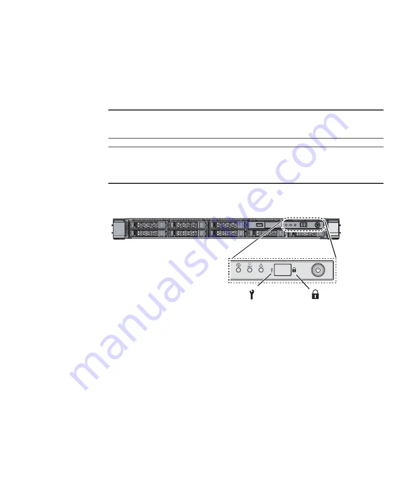
Service
Locked
6.2.2
Turning
on
the
input
power
and
starting
the
XSCF
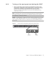
1.
Set
the
mode
switch
on
the
operation
panel
to
the
Service
position.
For
a
building
block
configuration,
set
the
mode
switches
on
the
master
chassis
and
the
chassis
that
has
the
standby
XSCF
to
the
Service
position.
The
Service
position
is
indicated
by
a
wrench
icon.
The
Locked
position
is
indicated
by
a
lock
icon.
Figure
6-1
Mode
switch
on
the
operation
panel
of
the
SPARC
M10-1
Chapter
6
Performing
an
Initial
System
Diagnosis
179
Summary of Contents for M10 Series
Page 1: ...Fujitsu M10 SPARC M10 Systems Installation Guide Manual Code C120 E678 12EN July 2015 ...
Page 10: ...Fujitsu M10 SPARC M10 Systems Installation Guide July 2015 x ...
Page 156: ...Fujitsu M10 SPARC M10 Systems Installation Guide July 2015 142 ...
Page 176: ...Fujitsu M10 SPARC M10 Systems Installation Guide July 2015 162 ...
Page 208: ...Fujitsu M10 SPARC M10 Systems Installation Guide July 2015 194 ...
Page 240: ...Fujitsu M10 SPARC M10 Systems Installation Guide July 2015 226 ...
Page 252: ...Fujitsu M10 SPARC M10 Systems Installation Guide July 2015 238 ...
Page 290: ...Fujitsu M10 SPARC M10 Systems Installation Guide July 2015 276 ...
Page 310: ...Fujitsu M10 SPARC M10 Systems Installation Guide July 2015 296 ...
Page 336: ...Fujitsu M10 SPARC M10 Systems Installation Guide July 2015 322 ...
Page 368: ...Fujitsu M10 SPARC M10 Systems Installation Guide July 2015 354 ...
Page 374: ...Fujitsu M10 SPARC M10 Systems Installation Guide July 2015 360 ...


