background image

Summary of Contents for M3093E

Page 1: ...FUfTSU M3093E IMAGE SCANNER OPERATOR S GUIDE 50FH5014E 04 ...

Page 2: ...e bruits radloelectriques depassant les limites applicables aux appareils numeriques de la classe A prescridtes dans le Reglesment sur le brouillage radio ledrique edict4 par le ministere des Communicationsdu Canada in accordance with such laws FUJ TSU L M TiD 1 The contents of this manual is subject to change without prior notice authonzatlon from the appropriate governmental authontles All Right...

Page 3: ...Operator Panel 4 2 4 2 1 Switchoperation 4 2 4 2 2 Flow chart of operator panel 4 3 4 2 3 Details of indication and operation of the panel 4 4 4 3 ADF Paper Chute Setting 4 16 4 3 1 ADF paper chute setting 4 16 4 3 2 Output stacker installation 4 16 4 3 3 Output extensions installation 4 17 4 3 4 Input extensions installation 4 18 4 4 DocumentSettingMethod 4 18 4 4 1 Flat bed 4 18 4 4 2 Automaticd...

Page 4: ...CHAPTER 6 TROUBLESHOOTING 6 1 CHAPTER 7 CLEANING 7 1 7 1 Cleaning Document Cover and Document Board Glass 7 1 7 2 Cleaning the ADF Section 7 1 50FI15014E 01 ...

Page 5: ...gnal cable connection 2 8 Power cable connection 2 9 Carrier fixing pin installation 2 11 Repackaging l 2 11 Repackaging 2 2 12 Cleaning the document board glass 3 1 Power switch and indicator 4 1 Operatorpanel 4 2 ADF paper chute setting 4 16 Document setting on flat bed 4 18 Loadingthedocument 4 22 Jammedpaperremoval 4 24 Lamp unit removal 5 2 Replacementpflampunit 5 2 Padassemblyremoval 5 3 Cle...

Page 6: ...TABLES page 2 1 Checklist 2 5 50FH5014E 01 vii ...

Page 7: ...ge reading mechanism document feed mechanism microprocessor control circuit operator panel and power supply The features of this device are l A document as large as A4 size can be read l High speed reading less than 3 5 seconds for a ACsize document with 400 dpi 1 l High resolution reading 400 dpi l Compact desktop size l Automatic document feeder ADF 50FH5014E 01 l l ...

Page 8: ...operation 2 1 Precautions of Installation Pay attention to following matter before packaging and installation Do not install in a place where vibration may occur Keep the scanner out of the sun Do not install near a hear source To ensure proper air circulation do not place material around scanner Do not install in a humid or dusty place Do not use the wall socket with connecting devices which may ...

Page 9: ...ints 8 Pull up the carton to remove 0 Remove the upper retainers 0 Take out the accessories and test certificate 63 Take out the scanner Take out the scanner from vinyl bag and remove the protection tape 6 Check the accessories by refering to Figure 2 2 and Table 2 1 2 2 50FH5014E 01 ...

Page 10: ...I Accessories Jpper retainer L Scanner Lower retainer CL Upper retainer CR Test certificate Lower retainer CR Accessory retainer Lower carton Figure 2 1 Unpackaging 50FH5014E 01 2 3 ...

Page 11: ...ing Received Products Check that the following items have been received Fuses types For USA For Europe Extentions Power cable Test certificate CCD Adjustment Bracket Figure 2 2 Received products 2 4 50FN5014E 01 ...

Page 12: ...USA 2 2 Fuses 2 3 2A 2 OA For Europe 3 Stacker 1 4 CCD Adjustment Bracket 1 5 Extentions 2 2 4 Shipping Retainer Removal 0 Remove the document cover Open the document cover approximate 45 and pull it as shown in Figure 2 3 Document cover Figure 2 3 l ocument cover removal 50FH5014E 01 2 5 ...

Page 13: ... up the lamp cover Figure 2 4 Lamp cover removal C3 Pull out the shipping retainer Shipping retainer Figure 2 5 Shipping retainer remo val 8 Put in the lamp cover 2 6 6 Put on the document cover 50FH5014E 01 ...

Page 14: ...gure 2 6 describes parts names Document cover ADF Stacker ADF Chute Document pad Document board Glass I I Power switch _ _ f Operator panel Power Connector Signal connectors Figure 2 6 M3093E parts names 50FH5014E 01 2 7 ...

Page 15: ... scanner to the host computer with signal cables V and R Signal cable V Ggnal cable R Screw To host computer To host computer Figure 2 7 Signal cable connection Insert the two cables as shown in Figure 3 3 Fasten the two catches to signal cable V and fix signal cable R with the screws The other end of each cable should be attached to the host computer in the same way 2 8 50FH5014E 0 1 ...

Page 16: ...0 Insert the power cable into its connector on the rear of the image scanner Also insert the power cable into a power outlet with FG Figure 2 8 Power cable connection 50FH5014E 03 outlet 2 9 ...

Page 17: ...Insert the carrier fixing pin to the hole of the carrier see Figure 2 9 Put the lamp cover and the document cover Push down the chute and remove the stacker and ex tensions Set poly urethane foam on the upper cover and close the document cover see Figure 2 10 Tight the covers with adhesive tape see Figure 2 10 Put the scanner into the vinyl bag Put the scanner into the lower carton Put the accesso...

Page 18: ... EC Z 3 I Carrier fixing pin Figure 2 9 Carrier fixing pin installation Tape cusion to the document cover Push down and Tape the lamp cover Figure 2 10 Repackageing 1 To be taped 50FH5014E 03 2 11 ...

Page 19: ...Upper retainers Test certificate i i I rower retainer ttj Accessory retainer Figure 2 11 Repackaging 2 2 12 50FH5014E 03 ...

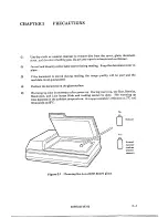
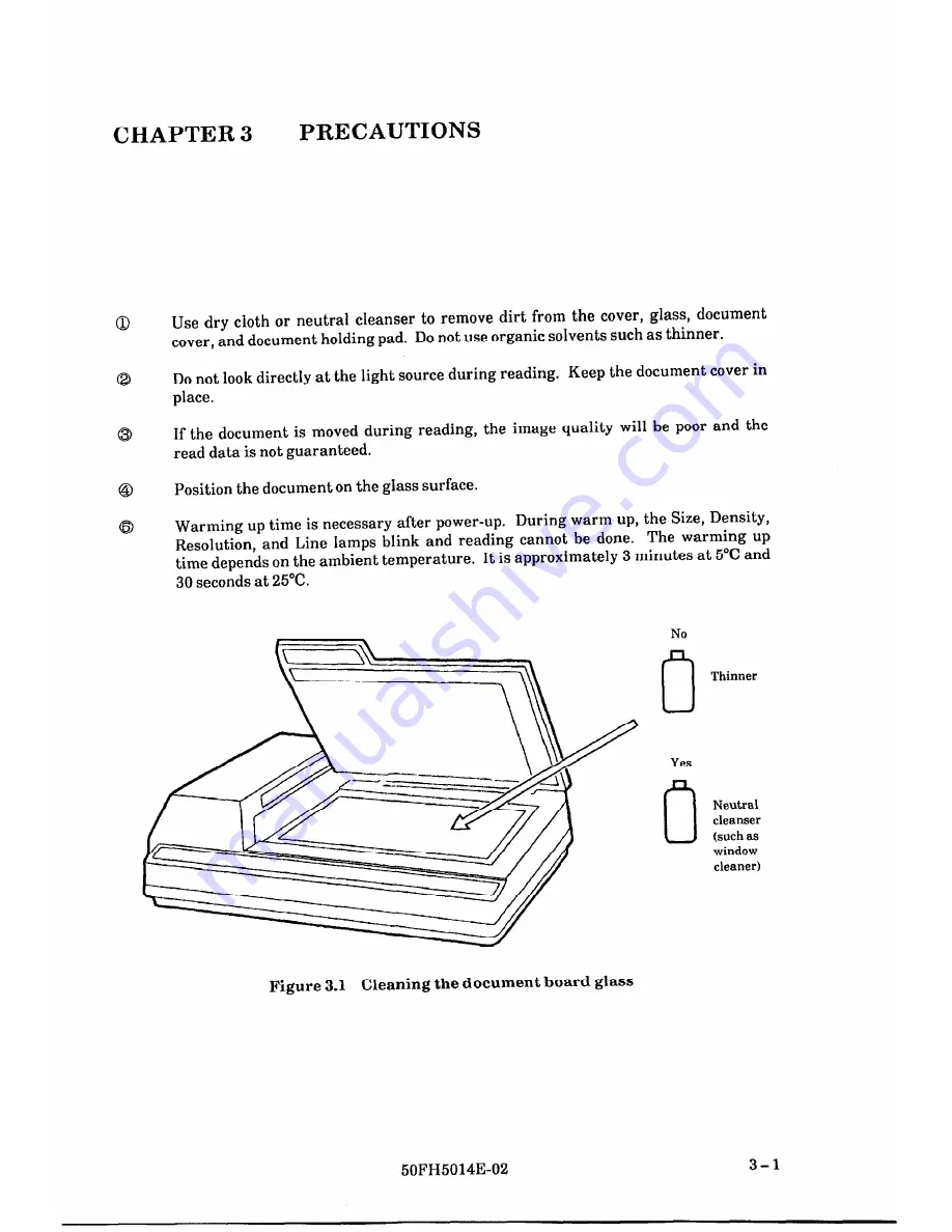
Page 20: ...uring reading the image quality will be poor and the read data is not guaranteed Position the document on the glass surface Warming up time is necessary after power up During warm up the Size Density Resolution and Line lamps blink and reading cannot be done The warming up time depends on the ambient temperature It is approximately 3 minutes at 5 C and 30 seconds at 25 C Figure 3 1 Cleaning the do...

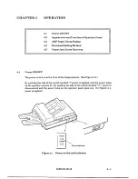
Page 21: ...he power switch is on the front of the image scanner See Figure 4 1 By pushing the side of the switch marked I power is applied and the power lamp on the operator panel is lit By pushing the side of the switch marked O power is disconnected and the power lamp on the operator panel goes out In Figure 4 1 power is applied Power Indicator Figure 4 1 Power switch and indicator 50FH5014E 02 4 l ...

Page 22: ... 1 1 or 1 2 when scanning mode is specified Mode switch Updates the scanning mode specification screen Select switch Updates the scanning mode specification Shift switch Changes the zoom factor Shift and Stop switches Resets the scanning mode to the default values Shift and Mode switches Changes from the scanning mode specification screen to the preceding screen Shift and Select switches Changes f...

Page 23: ...n 2 l i g y y Screen 3 I z 2 Screen 4 l g 9 Screen 5 1 v i j y q Screen 6 gj y 9 I I I I Screen 7 l I z b jy I I I I Screen 8 I I f reen8 1 I I I I I y c i IJNCHG CHG I I I I I I I iI I I I I i P j F i ii 83 UNCHG j i x I l j Mode switch pressed Screen 8 v Shift Mode switch f s Screen 8 6 Select switch pressed Screen 8 7 50FH5014E 01 4 3 ...

Page 24: ...screen 8 2 is indicated 4 2 3 Details of indication and operation of the panel a Screen 1 1 The ready 1 screen II l l Image processingCircuit IPC blink IPC installed U blink IPC not installed Density 11 nrl Light IKKl Somewhat light I n 0 Normal II 0 Somewhat dark AT Dynamic Threshold Resolution 400 400 dpi 300 300 dpi 240 240 dpi 200 200 dpi Type of Document L Line drawing P Harlftone A Auto disc...

Page 25: ...in this status changes the screen to the read mode specification change screen When image processing is specified press the select switch to change the display to screen 1 2 The ready 2 screen b Screen 1 2 The ready 2 screen 1 Overlayed pattern Horizontal line Vertical line S Angled line Dots pattern I Triangle pattern Lattice1 pattern Outline Not operated w4Il Operated W B conversion Mirror image...

Page 26: ... at the scanning system spec ification screen to change between FB and ADF Blinking mode is specified The default setting is FB Press mode switch to choose the desired scanning system and go on to next screen 4 Screen 3 Document size specification S i z e L G L T A 4 III Letter size is Blinking specified S i z e L T A 4 B 5 III A4 portrait is I specified Blinking S i z e A 4 B 5 A 1 5 l zI B5portr...

Page 27: ...ification screen changes cyclically r Line Photo Line Photo 1 The default setting is Line Photo When the image processing circuit is not installed the default setting is Line and Line Photo can not be selected Press the mode switch to choose the desired type and go on next screen 0 Screen 5 White level follower specification AE ON 0 F F This screen specifies if white level follower active The whit...

Page 28: ...acter is shown below n H n n 17 Somewhat dark n mHmB Dark Auto Dynamic threshold Press mode switch to choose the desired density and go on next screen h Screen 7 Resolution specification 1 2 0 0 4 0 0 v Blinking Res 400 3 0 0 I 2 III4 0 Blinking Res 3 0 0 2 4 0 Blinking Res 2 4 0 2 0 0 I Blinking 400 dpi is specified 300 dpi is specified 240 dpi is specified 200 dpi is specified 4 8 50FH5014E 02 ...

Page 29: ...ect switch at the image processing mode specification screen to alternately select UNCHG and CHG Press the mode switch at CHG to display the image processing screens Press the Mode switch with UNCHG selected to go on to next screen Note 1 When there are no image processing circuit no screens are displayed after this 2 Only 1 mode among Tone Outline Overlay can be changed from default If these mode...

Page 30: ...itch at the Zooming rate change screen to cyclically select The step is as shown 25 50 75 100 125 150 200 225 c400 375 t 350 3325 300 275 250 The default setting is 100 The zooming rate can be incremented in 1 steps using the Select switch To decrement the value in 1 steps press the Shift and Select switches at the same time Press the Mode switch to choose the currently displayed zooming factor an...

Page 31: ...n scanning direction Hor Zoomi n g1 11 0 0 Press Shift and Start switch at the Zooming rate change screen to cyclically select The step is as shown 25 50 75 100 125 150 200 225 c400 375 350 325 w 300 f 275 250 The default setting is 100 The zooming rate can be incremented in 1 steps using the Select switch To decrement the value in 1 steps press the Shift and Select switches at the same time Press...

Page 32: ...n q Reverse operation EI Mirror and reverse operation Screen 8 6 Outline specification Illust H U 0 I I Press the Select switch at the outline specification screen to alternately select n and El The brinking character is selected mode The default setting is n Press the Mode switch to choose the desired specification and go on to the next screen The meaning of the character indicated in the screen ...

Page 33: ...g 1 Blinking 0 v e r 1 a y 111111B i i I i 1 Blinking Blinking Blinking I Blinking Press the Select switch at the overlay specification screen to cyclically select The default mode is no operation no blinking R iiJ I1 No blinking 1 Press the Mode switch to choose the desired overlay pattern and go on to next screen 50FH5014E02 4 13 ...

Page 34: ...aper jam in ADF P a p e r Jam 6 ADF Cover open 1 lAl lF Cover 1 1 1 1 1 1 1 Open 1 1 1 1 7 Equipment Error Equipment Alarm Press the Select switch to display the error message 7 l Control system error EEPROM or RAM error Control Alarm 7 2 Driver system error The carrier does not return to the home position Mechanical Alarm 7 3 Option error Lamp error check 1 Olpltlilclalll I Alarm 4 14 50FH5014E 0...

Page 35: ... I lHlelaltlelrl lAlllalrlml 7 5 Carrier motor fuse brown I IFIBI lmloltlolrl lAlllalrlml I 7 6 ADF motor fuse brown AIDIFI lrnloltlolrl Alarm 7 7 Lamp driver fuse brown lLlalmlplflulslel Alarm 7 8 Lamp heater fuse brown Hlelaltlelrlflulslel Alarm 50FH5014E 01 4 15 ...

Page 36: ... 0 Hold the handle of document cover with one hand and grip the edge of ADF paper chute with another hand Raise up the ADF paper chute till hear the click sound When down the ADF paper chute push it down to the document cover 4 3 2 Output stacker installation 0 Lift the stacker and slightly bend it from its base When the documents reading using a ADF 4 16 50FH5014E 02 ...

Page 37: ...ut extensions installation 0 Lift the stacker 8 Grasp both sides of the extension and press the side edges inside as follows CB Insert the extension in the slots on the base of the stacker as follows 8 Release the extension and lower the stacker 50FH5014E 02 4 17 ...

Page 38: ...nsert it in to the slots on the back of ADF paper chute 2 Release the sides and pull the extension out until the edges are stopped by slots 4 4 Document Setting Method 4 4 1 Flat bed Document cover Reference mark Reference frame Document Figure 4 4 Document setting on flat bed 4 18 50FH5014E 02 ...

Page 39: ...y be moved During reading do not press or open the document cover Select the reading mode from the control panel and start scanning If portrait landscape is selected according to the document size or form reading time can be reduced The relationship between the document form and reading mode is as follows Landscape mode Portrait mode Flat bed Flat bed 63 After reading ends open the document cover ...

Page 40: ...he document upside down Arrange the document as shown below See the next page End Open the right and left guides of the ADF paper chute and set them approximately 5 mm wider than the document width Position the document face down and put the ends of the lower 2 or 3 sheets into the auto feeder hole Line up the guides with the document sides Skewing may occur if there is a gap between the guides an...

Page 41: ...sen the grip of your left hand and straighten the sheets as shown in c 5 Repeat operations 3 and 4 as often as necessary a b Cc Feed dir Reference r upper end Handling sheets Handling sheets Take a 2 to 4 mm thickness of sheets Lightly hold both ends with both hands Bend the sheets as shown Hold the sheets tightly with both hands then straighten the sheets The sheets swell and air is introduced be...

Page 42: ...ing the document 8 Select the reading mode from the control panel and start reading If selection of the document size or format portrait landscape is wrong reading of the entire document may fail so care must be taken The relationship between the document format and reading below Portrait mode Landscape mode y Paper chute mode is as shown Document I 4 22 Auto feeder unit 50FH5014E 02 ...

Page 43: ... bed for the following types of document a Wrinkled curled or folded documents b Transparent documents c Documents treated with a glossy coating d Damaged documents e Very thin documents f Very thick documents g Documents smaller than A5 size h Carbon paper or thermal paper i Cloth metal sheets OHP sheets photographs 0 Envelopes or pasted document k Documents of uneven thickness 50FH5014E 02 4 23 ...

Page 44: ...d paper with following procedure 1 2 3 4 5 Take out the document on the paper chute Open ADF unit with holding the metal part inside of the ADF cover lettered Up Remove jammed paper Close ADF unit Press Stop switch Figure 4 6 Jammed paper removal 4 24 50FH5014E 01 ...

Page 45: ...ical Alarm the lamp unit must be replaced with following procedure 1 Turn off the power 2 Power on with pressing Mode switch and Select switch 3 After the carrier moves to the center of Flat bed turn off the power LCD indicates Power off 4 Remove the document cover and lamp cover 5 Pull out the lamp unit Meshed parts in Figure 5 1 50FH5014E 04 5 l ...

Page 46: ...ent cover Carrier Guide rail k _mJ TGuiderail Figure 5 1 Lamp unit removal 6 Insert the lamp unit along the guide rails When insert pay attention not to touch plated area of the unit Plated area Figure 5 2 Replacement of lamp unit 5 2 50FH5014E 04 ...

Page 47: ...sheets feed error l Large skew 0 Open the ADF unit Hold both ends of the pad retainer to remove the pad assembly Figure 5 3 Pad assembly removal Notes 1 Do not bent or break the sheet when installing the pad assembly 2 Note the chamfer position of the sheet when installing the pad assembly 50FH5014E 04 5 3 ...

Page 48: ...ts such as thinner Dirt on glass surface Characters or Density setting error l Select suitable mode lines are not Halftone is set Dirt on l Clean the glass Use dry cloth or read well glass surface neutral cleanser Do not use organic solvents such as thinner Unclear image Document moved during l During reading close the cover and do Distorted reading not move the document image Document not in cont...

Page 49: ...e 0 0 0 0 8 l Documents is not fed smoothly Several documents is fed in a same time Reading result is not so good Open the ADF section Use the dry cloth or isopropyl alcohol to softly remove dirt and dust as follows Pad Cleaning direction is upper to lower Be careful not to hooking the pick spring when cleaning l Glass Cleaning direction is right to left Be careful not to hooking the sensor arm wh...

Page 50: ... Eject roller Pick roller Guide plate Figure 7 1 Cleaning the AIIF section 7 2 50FH5014E 02 ...

Page 51: ...esex UBll 1AB ENGLAND TEL 44 81 573 4444 FAX 44 81 573 2643 TLX 263871FELSPG FUJITSU DEUTSCHLAND GmbH Frankfurter Ring 21 1 8000 Mtinchen 40 F R GERMANY TEL 49 89 323780 FAX 49 89 32378100 TTX 897106 FDG D FUJITSU NORDIC AB Torggatan 8 171 54 Solna SWEDEN TEL 46 8 764 76 90 FAX 46 8 28 03 45 TLX 13411 FNAB S FUJITSU ITALIA S p A Via Melchiorre Gioia 8 20124 Milano ITALY TEL 39 2 6572741 FAX 39 2 6...

Page 52: ...s Fully 0 Reference 0 Maintaining Cl Operating q Covered Well o Illustrated Well l Organized i Clean uVhat isyour overall rating of this publication What isyour occupation 0 Very Good 0 Fair 0 Very Poor El Good 0 Poor Your other comments may be entered here Please be specific and give page paragraph and line number references where applicable Your Name 81Return Address Thank you for your interest ...

Reviews: