3 – 3
3.3
Connections
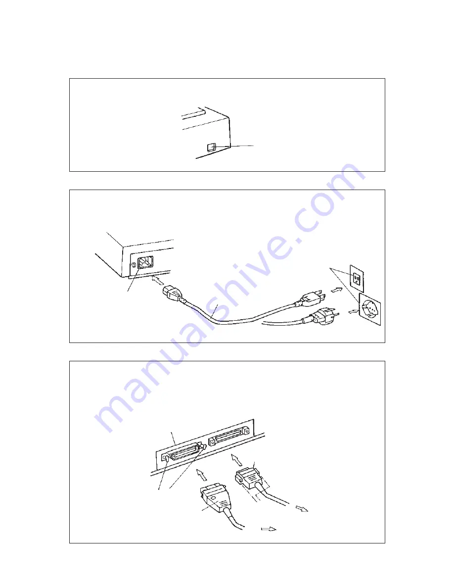
Connect the image scanner using the following procedure.
1
Set the power switch to off.
3
Connect the interface cables (for ).
Connect the interface cables to the interface connectors and fasten the cables
with catches and screws as shown below.
Connect the other end of each interface cable to the host computer.
2
Connect the power cable.
Connect the power cable to the power inlet on the back of the image scanner.
Connect the other end of the power cable to a power outlet.
Power inlet
for Europe
for North America
Back of the image scanner
Catches
Interface cable for video
Interface cable for RS232C
Screws
Power cable
Power outlet
To the host system
Power switch
Summary of Contents for M3097E
Page 1: ...C150 E048 02EN M3097E AND M3097G IMAGE SCANNER OPERATOR S GUIDE ...
Page 9: ...1 2 This page is intentionally left blank ...
Page 27: ...3 6 This page is intentionally left blank ...
Page 43: ...5 8 Glass Levers Openings Figure 5 7 Inserting the glass Close the ADF to lock ADF lever ...
Page 47: ...5 12 This page is intentionally left blank ...
Page 51: ...A 2 A 2 External Dimensions 173 696 497 Unit mm Figure A 1 External dimensions ...
Page 52: ......
Page 53: ......
Page 56: ......


