C141-E166
4-9
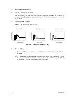
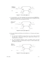
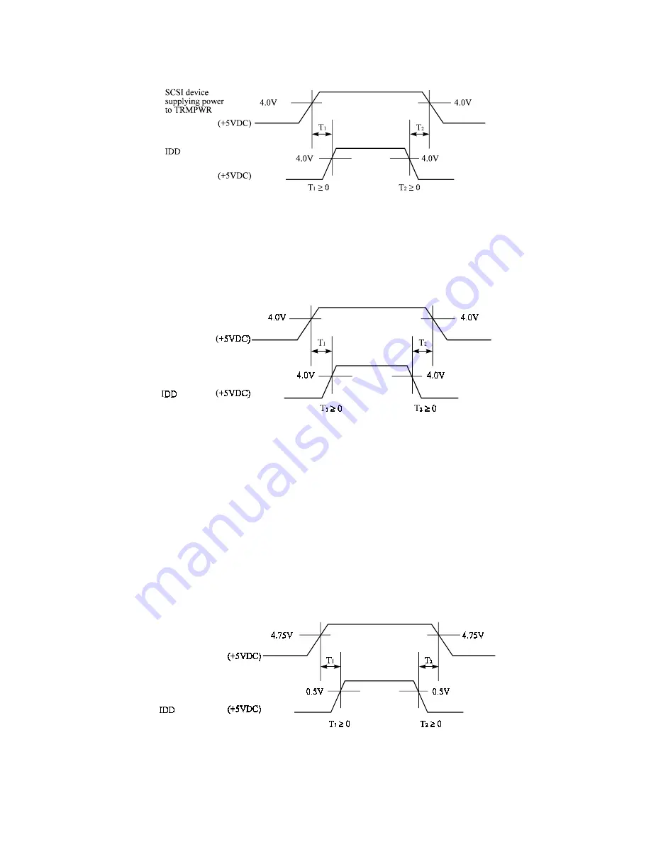
Figure 4.9
Power on/off sequence (1)
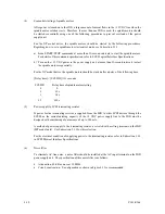
c) In a system which does not use the terminating resistor power supply signal (TERMPWR) on
the SCSI bus, the requirements for +5 VDC given in Figure 4.10 must be satisfied between the
IDD and the SCSI device with the terminating resistor circuit.
Figure 4.10 Power on/off sequence (2)
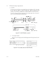
d) Between the IDD and other SCSI devices on the SCSI bus, the +5 VDC power on/off sequence
is as follows:
•
In a system with its all SCSI devices designed to prevent noise from leaking to the SCSI
bus when power is turned on or off, the power sequence does not matter if the
requirement in b) or c) is satisfied.
•
In a system containing an SCSI device which is not designed to prevent noise from
leaking to the SCSI bus, the requirement given in Figure 4.11 must be satisfied between
that SCSI device and the IDD.
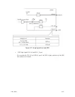
Figure 4.11 Power on/off sequence (3)
SCSI devices
without noise
leaking designed
SCSI devices with
the terminating
resistor
Summary of Contents for MAP3147NC - Enterprise - Hard Drive
Page 1: ...C141 E166 01EN MAP3147NC NP MAP3735NC NP MAP3367NC NP DISK DRIVES PRODUCT MAINTENANCE MANUAL ...
Page 10: ...This page is intentionally left blank ...
Page 14: ...This page is intentionally left blank ...
Page 18: ...This page is intentionally left blank ...
Page 36: ...This page is intentionally left blank ...
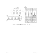
Page 66: ...4 14 C141 E166 Figure 4 17 External operator panel connector CN2 ...
Page 122: ...This page is intentionally left blank ...
Page 126: ...This page is intentionally left blank ...
Page 128: ...This page is intentionally left blank ...
Page 130: ...This page is intentionally left blank ...
Page 131: ......
Page 132: ......

