background image

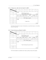
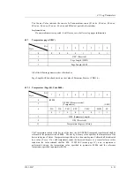
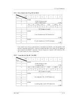
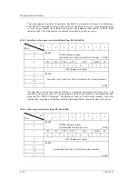
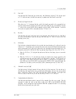
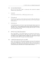
5.1  Sense Data

C141-E167

5 - 5

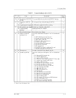
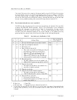
Table 5.1

Sense key

Sense

Key

Name

Explanation

0

NO SENSE

The specific sense key does not exist.

1

RECOVERED
ERROR

1) Indicates that the command which was executed last was terminated

normally with a recovery operation by the IDD. If multiple errors
which were successfully recovered from during processing of a
single command occurred, the last error to have occurred is
reported.

2) Rounding processing of the MODE SELECT parameter was

performed.

2

NOT READY

The disk drive is not in a state where it can be accessed.

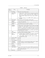
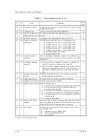
3

MEDIUM
ERROR

An irrecoverable error was detected due to a defect in the disk media or
an error in the recorded data.

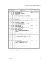
4

HARDWARE
ERROR

The IDD detected an error in the hardware for which recovery processing is
impossible during command execution or self-diagnosis.

5

ILLEGAL
REQUEST

An illegal value was detected in the parameter transferred in the CDB or
the specification in the command.  Also, an error in the LUN
specification.  If the IDD detects an illegal parameter in the CDB, it
terminates the command without changing the contents of the disk
media.  If an illegal parameter is detected in the parameters transferred
from the INIT in the DATA OUT phase, the contents of the disk media
may be changed by that command.

6

UNIT
ATTENTION

A UNIT ATTENTION condition occurred.  (See Section 1.5 concerning
details of the UNIT ATTENTION condition.)

7

DATA
PROTECT

1) An illegal operation was attempted in an area where a read or write

operation is prohibited.  In this case, that command is not executed.

2) A SET LIMITS command was issued 2 times in a group of

commands linked in a series.

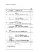
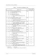
8

BLANK  CHECK

Not Used

9

(Reserved)

Not Used

A

COPY ABORTED

Not Used

B

ABORTED
COMMAND

The IDD terminated a command abnormally during execution.  Normally,
the INIT can attempt to recover by reissuing that command.

C

EQUAL

Not Used

D

VOLUME
OVERFLOW

Not Used

E

MISCOMPARE

During execution of a Byte Check with the VERIFY command, the data
transferred from the INIT were compared to the data read from the disk
drive, but they did not match.

F

(Reserved)

Not Used

Summary of Contents for MAP3147NC - Enterprise - Hard Drive

Page 1: ...C141 E167 01EN MAP3367 MAP3735 MAP3147 NP NC SERIES MAS3367 MAS3735 NP NC SERIES DISK DRIVES SCSI LOGICAL INTERFACE SPECIFICATIONS ...

Page 2: ...rt controls medical devices for life support or weapons firing controls where particularly high reliability requirements exist where the pertinent levels of safety are not guaranteed or where a failure or operational error could threaten a life or cause a physical injury hereafter referred to as mission critical use Customers considering the use of these products for mission critical applications ...

Page 3: ...C141 E167 Revision History 1 1 Edition Date Revised section 1 Added Deleted Altered Details 01 May 2002 1 Section s with asterisk refer to the previous edition when those were deleted ...

Page 4: ...This page is intentionally left blank ...

Page 5: ... index Chapter 1 Command Processing This chapter describes the basic logical specifications related to SCSI command processing in the disk drives Chapter 2 Data Buffer Management This chapter describes the data buffer configuration provided in the disk drives and concerning data transfer processing functions and cache operation Chapter 3 Command Specifications This chapter describes specifications...

Page 6: ...y this manual differs in its ending suffix Note 1 depending on its device type 3 types the electrical conditions of the SCSI interface used to connect the disk drive to the host system and its capacity and data format at the time it was shipped but in this manual except in cases where models need to be especially distinguished a representative model name Note 2 is used In addition these disk drive...

Page 7: ...367NP MAS3367NC MAS3735 MAS3735NP MAS3735NC MAP3367 MAP3367NP MAP3367NC MAP3735 MAP3735NP MAP3735NC MAP3147 MAP3147NP MAP3147NC Warning Indications The following warning indications are shown in this manual to prevent the user and other nearby persons or property from being injured or damaged Note Note indicates the most effective method of use or information that is of value to the user Requestin...

Page 8: ...AFT Information Technology SCSI 3 Parallel Interface American National Standards Institute ANSI T10 1236 D Rev 19 Information technology SCSI Primary Commands 2 SPC 2 American National Standards Institute ANSI T10 project 996D Rev 8C Information Technology SCSI 3 Block Commands SBC American National Standards Institute ANSI X3T10 994D Rev 18 Information technology SCSI 3 Architecture Model SAM Ame...

Page 9: ...tenance 7 Error Analysis 8 Principle of Operation SCSI Physical Interface Specifications 1 SCSI Bus 2 SCSI Messages 3 Error Recovery SCSI Logical Interface Specifications This Manual 1 Command Processing 2 Data Buffer Management 3 Command Specifications 4 Parameter Data Formats 5 Sense Data Error Recovery Methods 6 Disk Media Management MANUAL ORGANIZATION ...

Page 10: ...This page is intentionally left blank ...

Page 11: ...1 19 1 5 2 Response and release condition at UNIT ATTENTION condition hold state 1 20 1 5 3 UNIT ATTENTION condition multiple hold 1 22 1 6 Sense Data Hold State 1 22 1 6 1 Sense data hold condition 1 22 1 6 2 Response and release conditions at sense data hold state 1 22 1 7 Command Processing Exceptions 1 23 1 7 1 Overlapping commands 1 23 1 7 2 Illegal LUN specification 1 24 1 7 3 Reserved opera...

Page 12: ... 15 3 19 3 1 6 MODE SELECT EXTENDED 55 3 26 3 1 7 MODE SENSE 1A 3 28 3 1 8 MODE SENSE EXTENDED 5A 3 34 3 1 9 REZERO UNIT 01 3 35 3 1 10 START STOP UNIT 1B 3 36 3 1 11 RESERVE 16 3 37 3 1 12 RESERVE EXTENDED 56 3 40 3 1 13 RELEASE 17 3 41 3 1 14 RELEASE EXTENDED 57 3 42 3 1 15 REQUEST SENSE 03 3 42 3 1 16 LOG SELECT 4C 3 44 3 1 17 LOG SENSE 4D 3 48 3 1 18 PERSISTENT RESERVE IN 5E 3 49 3 1 18 1 PERS...

Page 13: ...ot Supported 3 72 3 2 10 SYNCHRONIZE CACHE 35 3 74 3 3 Format Commands 3 75 3 3 1 FORMAT UNIT 04 3 75 3 3 2 REASSIGN BLOCKS 07 3 85 3 3 3 READ DEFECT DATA 37 3 88 3 4 Maintenance Diagnostic Commands 3 92 3 4 1 SEND DIAGNOSTIC 1D 3 92 3 4 2 RECEIVE DIAGNOSTIC RESULTS 1C 3 98 3 4 3 WRITE BUFFER 3B 3 102 3 4 4 READ BUFFER 3C 3 107 3 4 5 READ LONG 3E 3 111 3 4 6 WRITE LONG 3F 3 112 3 4 7 WRITE SAME 41...

Page 14: ... recovered with possible delays Page 03 Code 0001 4 44 4 2 4 3 Total posted read errors Page 03 Code 0002 4 45 4 2 4 4 Total posted recoverable read errors Page 03 Code 0003 4 45 4 2 4 5 Total read bytes processed Page 03 Code 0005 4 46 4 2 4 6 Total posted unrecoverable read errors Page 03 Code 0006 4 46 4 2 5 Verify error count page X 05 4 47 4 2 5 1 Verify errors recovered without delays Page 0...

Page 15: ...itional information 5 11 5 2 INIT Error Recovery Methods Recommended 5 11 5 2 1 Termination status analysis and error recovery methods 5 11 5 2 2 Sense data analysis and error recovery methods 5 14 5 2 3 Error logging 5 21 5 3 Disk Drive Error Recovery Processing 5 22 5 3 1 Error states and retry processing procedures 5 22 5 3 2 Auto alternate block allocation processing 5 23 5 3 3 Error recovery ...

Page 16: ...ration 3 31 3 11 MODE SENSE EXTENDED command Group 2 parameter configuration 3 35 3 12 SET LIMITS command Specifying the range where access is permitted 3 73 3 13 FORMAT UNIT command parameter list configuration 3 78 3 14 Defect descriptor Byte distance from index format 3 80 3 15 Defect descriptor physical sector address format 3 81 3 16 REASSIGN BLOCK command defect data list configuration 3 86 ...

Page 17: ...us 5 12 Tables 1 1 Responses to Link Specification Commands 1 10 1 2 Types of Command and Disconnect Processing 1 12 1 3 Sense data in not ready state 1 25 1 4 Outline of SCSI Bus Error Recovery Processing 1 26 1 5 Outline of disk drive error recovery processing 1 27 1 6 Reset processing during write 1 28 3 1 MODE SENSE Data Type Specifications 3 30 3 2 Persistent reservation type codes 3 55 3 3 P...

Page 18: ...This page is intentionally left blank ...

Page 19: ...commands from INIT initiator to the IDD are accomplished by the CDB Command Descriptor Block The CDB is information transferred from INIT to TARG in the COMMAND phase In a number of commands the parameters which are necessary for command execution in the DATA OUT phase may be specified in addition to the CDB specification Details concerning these are described in the specifications for each indivi...

Page 20: ...LUN 0 0 0 0 0 2 Logical Block Address MSB 3 Logical Block Address 4 Logical Block Address 5 Logical Block Address LSB 6 Transfer Data Length MSB 7 Transfer Data Length LSB 8 Transfer Data Length MSB 9 Transfer Data Length LSB 10 0 0 0 0 0 0 0 0 11 Control Byte Figure 1 3 12 Byte CDB Basic Format The meanings of each of the fields in the CDB are explained below Depending on the type of command the ...

Page 21: ... message is used the value of the CDB s LUN field is ignored when the LUN is specified Note It is possible that the definition of this field may be changed in future SCSI standards It is recommended that the LUN be specified using the IDENTIFY message and that a zero be specified in this CDB field 3 Logical block address This field shows the leading logical data block address of the data block on ...

Page 22: ...between the INIT and the IDD expressed as the number of bytes When 0 is specified in this field data transfer is not executed except in cases where it is expressly stated in the individual command specifications in Chapter 3 In commands which send parameters necessary for executing a command from the INIT to the IDD this field is called the Parameter List Length and it specifies the total number o...

Page 23: ...o even in cases where there is an error in the CDB s specifications in a command accompanying the DATA OUT phase the DATA OUT phase is executed after the COMMAND phase is terminated but those data are not used For example if there is an error in the CDB specification of a WRITE command the IDD executes the transfers several bytes of data the data length to be transferred is not specified but those...

Page 24: ...ge an ABORT TASK message a CLEAR TASK SET message a TARGET RESET message a RESET condition or a SCSI bus error state etc the status byte for that command is not reported After the TARG reports the status byte in the STATUS phase it will always send a TASK COMPLETE message or a LINKED TASK COMPLETE WITH FLAG message to notify the INIT of the validity of the status byte Bit 7 6 5 4 3 2 1 0 0 0 Statu...

Page 25: ...e this status is not reported 4 BUSY status This status indicates that the IDD is in the busy state and it cannot receive a new command Normally an INIT that receives this status reissues the original command after waiting an appropriate period of time The IDD reports the BUSY status in the following cases the command stack function is explained in Section 1 4 a If the IDD receives a new command w...

Page 26: ... single command processing examples which are the most basic operations on the SCSI bus Furthermore if disconnect processing is permitted it may be accompanied by disconnect reconnect processing during the command execution depending on the type of command but this operation is omitted in the following explanation The disconnect function is described in Section 1 3 3 1 The INIT sets the initial va...

Page 27: ...ly the TARG reports the INTERMEDIATE status in the STATUS phase to the INIT At this time the command link function becomes effective 6 The TARG informs the INIT of the LINKED TASK COMPLETE or the LINKED TASK COMPLETE WITH FLAG message depending on the value of the Flag bit in the control byte of the CDB When the INIT has received the LINKED TASK COMPLETE WITH FLAG message the command data and stat...

Page 28: ...OMPLETE Not Effective Queue Full State QUEUE FULL TASK COMPLETE Not Effective Only a single logical unit can operate a series of linked commands When the IDD receives the first command the logical unit specified by the IDENTIFY message or the LUN field of the CDB becomes the object of operation in a series of linked commands and the values specified in the LUN field in the second and subsequent CD...

Page 29: ...1 Disconnect permission conditions and commands with executing disconnect process If all of the conditions shown below for permitting a disconnect are satisfied the IDD executes disconnect processing However As shown in Table 1 2 disconnect processing may be valid or invalid and the disconnect processing execution timing may differ depending on the type of command Conditions for Permitting a Disco...

Page 30: ...T DEVICE IDENTIFIER A4 O START STOP UNIT 1B O SYNCHRONIZE CACHE 35 O T TEST UNIT READY 00 O V VERIFY 2F O W WRITE 0A O WRITE AND VERIFY 2E O WRITE BUFFER 3B O WRITE EXTENDED 2A O WRITE LONG 3F O WRITE SAME 41 O Note 1 Commands without executing disconnect processing In cases only where commands are issued without a tag queuing processing see Section 1 4 and disconnect processing cannot be performe...

Page 31: ... phase execution is completed In this case the IDD switches from the COMMAND phase to the MESSAGE IN phase and sends the DISCONNECT message to the INIT 4 Disconnect processing procedure after data transfer execution For commands which accompany a data transfer disconnect processing may be performed during DATA IN or DATA OUT phase execution or after transfer of the last data is completed In this c...

Page 32: ...when processing on the SCSI bus is necessary and gets the SCSI bus control right then reconnects with the INIT in the RESELECTION phase 2 After that the IDD sends the IDENTIFY message to the INIT and notifies it of the logical unit number LUN necessary for reconnection processing If a tagged queuing command is executed the IDD sends the SIMPLE message to inform the INIT of the tag ID The INIT read...

Page 33: ...message or PARALLEL PROTOCOL REQUEST message and determine parameters necessary for executing the synchronous mode transfer When exchange of the WIDE DATA TRANSFER REQUEST message or PARALLEL PROTOCOL REQUEST message is completed if the synchronous mode has been established between the INIT and IDD previously note that the asynchronous mode is set The INIT which uses wide mode data transfer normal...

Page 34: ...d SCSI Messages SYNCHRONOUS DATA TRANSFER REQUEST WIDE DATA TRANSFER REQUEST PARALLEL PROTOCOL REQUEST in Chapter 2 of SCSI Physical Interface Specifications for further details 1 4 Command Queuing Function The IDD equips a command queuing function Through queuing of commands the IDD can receive multiple commands in advance and execute them There are two methods used in the queuing function tagged...

Page 35: ...us without queuing the received command except the case described in item 1 in following Note during executing or queuing command already If this is not the case the received command is executed immediately If the IDD is reserved If the IDD has been reserved by an INIT using the RESERVE command and receives a TEST UNIT READY command after that when that command conflicts with the reserved state it...

Page 36: ...ique tags If an ORDERED message is used the IDD executes the other commands not included in the ORDERED message in the order in which they are received All commands received with a SIMPLE message before commands are received with an ORDERED message are executed before those commands received with the ORDERED message All commands with SIMPLE messages received after commands received with the ORDERE...

Page 37: ...age the IDD rejects the message with the MESSAGE REJECT message processes the accompanying command as an untagged command The ABORT TASK SET ABORT TASK TARGET RESET or CLEAR TASK SET message is used to clear some or all of the commands in the queue See SCSI Physical Interface Specifications for details If 0001 is specified in the Queue algorithm modifier of the control mode page the IDD performs c...

Page 38: ...ATTENTION condition hold state for an INIT that issues a CLEAR TASK SET message an INIT that issues a MODE SELECT or MODE SELECT EXTENDED command or an INIT that releases the sense hold state 4 Changed operating definition When the operation mode is changed by the CHANGE DEFINITION command the UNIT ATTENTION condition is generated for all INITs 1 5 2 Response and release condition at UNIT ATTENTIO...

Page 39: ...on hold can be prohibited by the specification of the CHANGE DEFINITION command When the CHECK CONDITION status response is prohibited the IDD executes the commands it receives normally except in the case of a RESERVATION CONFLICT status BUSY status or QUEUE FULL status In this case the UNIT ATTENTION condition for the INIT that issued that command is cleared See Section 3 1 4 CHANGE DEFINITION co...

Page 40: ...nerated for the command that was terminated by the CHECK CONDITION status 2 If a fatal error occurs on the SCSI bus and the IDD forcibly enters the BUS FREE phase sense data is generated for the command that was being executed on the SCSI bus However if the LUN cannot be identified by the point when the error occurs the IDD does not generate sense data 3 Since it is impossible for reconnection pro...

Page 41: ...he sense data hold state 1 7 Command Processing Exceptions 1 7 1 Overlapping commands If the following state occurs the IDD recognizes that overlapping commands have been generated and the command is terminated abnormally 1 During the IDD is executing or queuing an untagged command the INIT that issued that command before the completion of the command execution issues either an untagged command or...

Page 42: ... executed normally even if the LUN specification is illegal However the sense data transferred to the INIT for that command indicates that the LUN specification is illegal ILLEGAL REQUEST 5 Logical unit not supported 25 00 3 If an illegal LUN is specified for a command other than the INQUIRY command or REQUEST SENSE command that command is terminated abnormally with a CHECK CONDITION status The se...

Page 43: ...e of the IDD as shown in Table 1 3 Table 1 3 Sense data in not ready state IDD State Sense Key Sense Code Spindle motor not rotating at normal speed NOT READY 2 Logical unit not ready 04 01 Reading system information have not completed NOT READY 2 Logical unit not ready 04 01 Reading system information failed HARDWARE ERROR 4 Logical unit failed self configuration 4C nn 2 Commands that can be exec...

Page 44: ... INIT can specify detailed parameters related to error recovery processing and whether or not there is a report for errors which were successfully recovered by using the MODE SELECT or MODE SELECT EXTENDED command It can also save those parameters in accordance with INIT specifications in the system space on the disk media and can change them temporarily without saving them After the power is swit...

Page 45: ...positioning to the data block on the disk or initialization of the positioning control system The INIT can use the MODE SELECT parameter Page 1 read write error recovery parameter Page 7 verify error recovery parameter and Page 21 additional error recovery parameter to control the retry count However use the default value specified by the IDD in general operation Table 1 5 Outline of disk drive er...

Page 46: ...n sends the ABORT TASK SET message to the TARG Also if there is a disconnect in effect after the INIT selects the TARG an ABORT message in the case of an untagged command or an ABORT TASK message in the case of a tagged command is sent following an IDENTIFY message which specifies the object logical unit or the INIT waits until a reconnection request occurs then sends an ABORT TASK SET message or ...

Page 47: ...n saved or not it is necessary for the INIT to confirm the status by the MODE SENSE command or the LOG SENSE command or reissue the command SYNCHRONIZE CACHE Data blocks which are currently being written are processed normally including the ECC portion and the command is halted at the point when that processing is completed Not all the data which is the write object will necessarily be written to ...

Page 48: ...n the power is switched on or during processing of specific commands but it cannot be accessed directly by the user Figure 1 5 shows the data space configuration on the disk drive The number of cylinders allocated to user space can be referred by the user MODE SENSE or MODE SENSE EXTENDED command A spare sector area alternate area for use as alternate sectors for defective sectors is allocated in ...

Page 49: ...49166 TBD TBD m 8 4 2 TBD TBD x 18 TBD Physical cylinder Zone 0 Zone x 1 Zone 1 Cell 0 Cell 1 Track 0 Track m 1 Track 1 Cylinder a 1 Cylinder 0 Cylinder 0 Cylinder 0 Track 0 Alternate cylinder b 1 b cylinders c cylinders Last cylinder d 1 Last cylinder Alternate cylinder User space System space a a a Figure 1 5 Data space configuration ...

Page 50: ...al data blocks are allocated to sector numbers in ascending order 2 Within the same head of the same cell succeeding logical data blocks are allocated to the sectors in each track according to 1 in the ascending order of cylinder numbers 3 Within the next head of the same cell succeeding logical data blocks are allocated to the sectors in each track according to 1 and 2 in the ascending order of t...

Page 51: ...t Out ring buffer with one port allocated for transfers with the disk media and the other port for data transfers with the SCSI bus Mutual ports operate asynchronously and since it is possible to efficiently absorb variations in data transfer speed between the ports the INIT can perform data transfer operations with the IDD while being virtually unaware of differences between the SCSI bus data tra...

Page 52: ...cts the data in the data buffer 3 When the IDD has read the amount of data specified by the buffer full ratio in the MODE SELECT parameter see Section 2 1 2 to the data buffer it performs reconnection processing with the SCSI bus and begins transferring data to the INIT SCSI bus from the data buffer while continuing to read subsequent data blocks to the data buffer 4 If the data transfer capacity ...

Page 53: ...ferred from the INIT are stored temporarily in the data buffer they are written to the disk media The basic write operation procedure is as shown below 1 When the IDD receives a command and disconnects it immediately reconnects and enters the DATA OUT phase and stores data transferred from the INIT to the data buffer data pre fetch At this time the IDD locates the position of the data block on the...

Page 54: ...he command is completed From then on disconnection reconnection and data transfer are repeated until transfer of all the blocks of data specified in the command is completed 5 When writing of all the specified data is completed the IDD reports the status and terminates the command Notes 1 If the amount of transfer data specified in a command is smaller than the capacity of the cache segment all th...

Page 55: ...to start reconnection to perform data transfer to the INIT in a READ or READ EXTENDED command The value specified in this parameter n shows the amount of data read to the IDD s data buffer from the disk media as a proportion n 256 of the total capacity of the data buffer until reconnection processing with the SCSI bus is started Note If it is possible to transfer the amount of data specified in th...

Page 56: ...r of the succeeding data Note If the value specified for the buffer full ratio or the buffer empty ratio is not within double the integral boundary of the logical data block length the IDD rounds up the specified value to the nearest data block boundary In addition if zero is specified for any of these parameters the IDD an appropriate value for the parameter that is determind by IDD 2 2 Look Ahea...

Page 57: ...ch exist in the data buffer and which are objects of caching in item 1 data which are not accessed from the disk media but are transferred to the INIT from the data buffer are as described below a Data read by a READ or a READ EXTENDED command and which have been read to the data buffer by Look Ahead are data which are objects of caching Depending on the timing for halting Look Ahead it is possibl...

Page 58: ...VE DIAGNOSTIC RESULTS RELEASE EXTENDED REPORT DEV ID RESERVE EXTENDED SEND DIAGNOSTIC SET DEV ID START STOP UNIT WRITE BUFFER WRITE LONG WRITE SAME c If the data buffer where data which are objects of caching are stored is used by any of the following commands the data existing in that data buffer which are objects of caching are disabled READ WRITE EXTENDED READ EXTENDED WRITE AND VERIFY WRITE VE...

Page 59: ...d 4 5 Prefetch suppressed block count Default X FFFF Variable X 0000 6 7 Minimum prefetch Default X 0000 Variable X 0000 8 9 Maximum prefetch Default X 00xx Variable X 0000 10 11 Maximum prefetch limit block count Default X FFFF Variable X 0000 12 FSW LBCSS DRA VS VS Reserved Default 1 0 0 0 0 0 0 0 Variable 0 0 0 0 0 0 0 0 13 Cache segment count Default X 08 Variable X 3F 14 15 Cache segment size...

Page 60: ...d operation is halted at the point when reading of the specified amount of data at the minimum pre fetch volume is completed then execution of the new command starts When there are no commands that need to be newly executed the data look ahead operation is continued even after the volume of data specified as the minimum amount of pre fetch data have been read until one of the following conditions ...

Page 61: ... cache function is permitted data transferred form the INIT by a WRITE or WRITE EXTENDED command are written to the disk media after the GOOD status is reported so when an unrecoverable write error is detected in that write operation sense data is generated When those sense data is being held the IDD ordinarily responds to the command that is executed next by a CHECK status deferred error notifyin...

Page 62: ...This page is intentionally left blank ...

Page 63: ... 0 2 0 0 0 0 0 0 0 0 3 0 0 0 0 0 0 0 0 4 0 0 0 0 0 0 0 0 5 0 0 0 0 0 0 0 Link This command checks the status of the disk drive This command is executed immediately without queueing in a system which issues only commands with no tags or links If the IDD is in the ready state and it is possible for it to be used by the application client which issues this command a GOOD status is reported for this c...

Page 64: ...is impossible to send INQUIRY data because of an IDD hardware error An unrecoverable error was detected on the SCSI bus An error detected during command execution was recovered in the IDD s error recovery processing Retry but the mode which reports RECOVERED ERROR is specified in the MODE SELECT parameter Applicability to overlapping command exception conditions See Section 1 7 1 The functions whi...

Page 65: ...IDD transfers the kind of the VPD information b If the EVPD bit is zero and the CmdDt bits is one this field specifies the operation code CDB byte 0 of commands generated command supported data 4 Transfer Byte Length Byte 4 of the CDB the Transfer Byte Length field shows the number of bytes of standard INQUIRY data or VPD information that the application client can receive by this command The IDD ...

Page 66: ...0 0 0 SCSI 3 0 0 0 0 0 0 0 0 SCSI 1 CCS Reserved Port DualP ACKB REQB Addr32 Addr16 SCSI 2 0 0 0 1 0 0 0 0 0 1 BQue EncServ VS MultiP MCHNGR Obsolete Addr16 SCSI 3 6 0 0 0 0 0 0 0 0 1 0 0 0 0 0 0 0 0 SCSI 1 CCS RelAdr WBus32 WBus16 Sync Linked TTD CmdQue SftRe SCSI 2 0 0 0 1 1 1 0 1 0 RelAdr Obsolete Wbus16 Sync Linked TranDis CmdQue VS SCSI 3 7 0 0 0 1 1 1 0 1 0 8 9 15 FUJITSU Vendor ID ASCII 16 ...

Page 67: ...n the other hand when a LUN other than 0 is specified the IDD reports 1 1 1 1 1 undefined device as the device type code At this time the Qualifier field is 0 1 1 Therefore byte 0 indicates X 7F c RMB bit When this bit is 1 it indicates that the storage media is a removable disk device The IDD is a fixed disk device so this bit is always reported as 0 d Version The VERSION field indicates the impl...

Page 68: ...ssign LUN 0 1 Byte 5 SCCS SCC support Embedded storage array controller equipment 0 Byte 6 BQue Basic queuing Combination with CMDQUE 0 EncServ Enclosure service Enclosure service 0 MultiP Multi port Supported multi port 0 MChngr Medium changer Medium Changer 0 Addr16 Wide SCSI address 16 16 bit SCSI addressing 0 1 Byte 7 RelAdr Relative addressing Relative logical block addressing 0 WBus16 16 bit...

Page 69: ...32 32 bit wide data transfer Data transfer on a 4 byte bus 0 WBus16 16 bit wide data transfer Data transfer on a 2 byte bus 0 1 Sync Scychronous data transfer Data transfer in the synchronous mode 1 Linked Linked command Command link function 1 TTD Target transfer disable Target transfer disable message 0 CmdQue Command queuing Tagged command queuing feature 1 SftRe Soft Reset Soft reset condition...

Page 70: ...e Supported bit This bit of one indicates that the device server supports the quick arbitrate feature A value of zero indicates that the device server does not support the quick arbitrate feature n IUS Information unit supported bit This bit of one indicates that the device server supports information units A value of zero indicates that the device server does not support information units o Versi...

Page 71: ...ata b Support This field indicates the value defined below Support Bit 2 1 0 Description 0 0 0 Data about the requested SCSI operation code is not currently available 0 0 1 The device server does not support the tested SCSI operation code All data after byte 1 is undefined 0 1 0 Reserved 0 1 1 The device server supports the tested SCSI operation code in conformance with an SCSI standard 1 0 0 Vend...

Page 72: ...ueried the usage map contains a zero in the corresponding bit position The usage map bits for a given CDB field all have the same value Thus the CDB usage bit map for Inquiry command for a device server that implements command support data but not vital product data is 12h 02h FFh 00h 07h 7 VPD information When 1 is specified in the EVPD bits of the CDB the VPD information described below is trans...

Page 73: ... field in byte 3 indicates the length byte length after byte 4 This value has no relationship to the specification in the Transfer Byte Length in the CDB but indicates the length of this VPD information and is always X 03 Total data length 7 bytes Byte 4 and subsequent bytes list all the VPD information page codes supported by the IDD with the VPD page code indicated in ascending order in each byt...

Page 74: ... 0 Qualifier Device Type Code 1 X C0 Page Code 2 X 00 3 X 04 Page Length 4 0 0 0 WDTR UNTAIN SDTR RSRTY 0 5 PHSCRC AGD ACE 0 0 0 RTD 6 X xx Spindle Motor Start Delay Timing 7 X 00 Reserved Figure 3 5 VPD information operation mode The values indicated in the Qualifier and Device Type Code fields in byte 0 are the same as those in the previously mentioned standard INQUIRY data The Page code field i...

Page 75: ...bit is 1 the logical block address and block length byte length of data blocks which satisfy either of the following conditions is transferred to the INIT The data block on the track where the specified block exists which is just before the block where the first alternate sector processing not including defective block sector slip processing is implemented However when alternate sector processing ...

Page 76: ...0 0 0 0 0 0 0 5 0 0 0 0 0 0 0 0 6 0 0 0 0 0 0 0 0 7 0 0 0 0 0 0 0 0 8 Parameter List Length 9 0 0 0 0 0 0 0 Link This command changes the IDD s SCSI level and the operation mode The INIT can know the SCSI level and operation mode that the IDD is currently using by the INQUIRY command Standard Inquiry Data and VPD Information Operation Mode Page Page code X C0 If the Save bit of CDB byte 2 specifie...

Page 77: ... List Length field in CDB byte 8 If zero is specified in the Parameter List Length field the command is terminated normally with only the SCSI level being changed When changing the operation mode the Parameter List Length field must always be specified by the length 8 defined by the operation parameter described later If a value other than the defined length in the Parameter Byte Length field is s...

Page 78: ...ONDITION status ILLEGAL REQUEST 5 Invalid field in parameter list 26 00 and the operation mode are not changed 2 Parameter list a WDTR wide data transfer request Effective for 16 bit SCSI devices only This specifies whether or not a wide mode data transfer request from the IDD is permitted If this bit is set to 1 also set SDTR to 1 If only this bit is set but SDTR is not set error code 5 26 00 is ...

Page 79: ...T condition occurs or when the first command is received following reception of a BUS DEVICE RESET message if a SYNCHRONOUS DATA TRANSFER REQUEST SDTR message is not sent by the INIT the IDD sends the SDTR message and attempts to establish synchronous mode data transfer 0 Prohibited Even if it is necessary to establish synchronous mode data transfer no SDTR message is sent from the IDD However if ...

Page 80: ... at shipping time The IDD ignores this specification and operates with the settings specified at shipping h RTD reselection timeout delay This specifies the reselection timeout delay time Bit 1 Bit 0 Reselection Time out Delay 0 0 250 ms 0 1 3 ms 1 0 Reserved 1 1 Reserved Set at shipping time i Spindle motor start delay time This specifies the time after power on until the motor starts The IDD s m...

Page 81: ...save pages bit in CDB byte 1 specifies whether or not to save the MODE SELECT parameters specified in this command on the disk It is possible for the IDD to save all the MODE SELECT parameters described in the Page Descriptor except for those on page C but this bit s specification is valid only for parameters other than Format parameters Page 3 and Drive parameters Page 4 excluding byte 17 If 1 is...

Page 82: ...ve values exist and no MODE SELECT command is being issued The IDD has a common set of Current Save and Default values of all the MODE SELECT parameters for all the INITs When the IDD s power is switched on when a RESET condition occurs or when the IDD receives a BUS DEVICE RESET message the Current MODE SELECT parameter values are changed to the Save parameter values if they exist and are changed...

Page 83: ...which can be changed by the INIT as desired parameters which the INIT cannot change which whose values are determined by the IDD unilaterally and parameters which can be changed by the INIT within certain appropriate limits The IDD also contains parameter fields which are applicable for rounding processing rounding up or rounding down of parameter values specified by the INIT to values which the I...

Page 84: ...elds which are the object of rounding processing are explained in the descriptions of each page descriptor in this item Figure 3 8 shows the data configuration of the parameter list transferred by the INIT in this command The parameter list is configured from header 4 bytes in length followed by a block descriptor with a length of 8 bytes This is followed by one or more page descriptors or when th...

Page 85: ...ich follows the header not including the length of the Page descriptor It is possible to define only 1 Block descriptor to the IDD and either X 00 or X 08 must be specified in this field When X 00 is specified in this field it indicates that the Block descriptor is not included in the parameter list transferred from the INIT and the Page descriptor follows immediately after the Header b Block desc...

Page 86: ...block count is rounded to the maximum value that is realizable There is a rounding processing report in this case If zero is specified for the Data block count or when the block descriptor is not specified the IDD retains its current capacity if the block size or alternate sector count has not changed If the Data block count is set to zero and the Data block size or alternate sector count has chan...

Page 87: ...is not supported by the IDD is specified the command is terminated with a CHECK CONDITION status ILLEGAL REQUEST 5 Invalid field in parameter list 26 00 and all the MODE SELECT parameters transferred in the command are disabled Parameter Byte Length Header 4 Block Descriptor 8 or 0 Page Descriptor Page 1 Read Write Error Recovery Parameter 8 or 12 Page 2 Disconnect Reconnect Parameter 12 or 16 Pag...

Page 88: ...d the variable column shows whether or not it is possible to vary that parameter 1 indicates that it can be varied The INIT can know those values and attributes by using the MODE SENSE or MODE SENSE EXTENDED command 3 1 6 MODE SELECT EXTENDED 55 Bit Byte 7 6 5 4 3 2 1 0 0 X 55 1 LUN PF 0 0 0 SP 2 0 0 0 0 0 0 0 0 3 0 0 0 0 0 0 0 0 4 0 0 0 0 0 0 0 0 5 0 0 0 0 0 0 0 0 6 0 0 0 0 0 0 0 0 7 Parameter Li...

Page 89: ...fer are the same as in the case of the Group 0 MODE SELECT command The contents of the other parameters Block descriptor Page descriptor are also the same as in the case of the Group 0 MODE SELECT command Header Bit Byte 7 6 5 4 3 2 1 0 0 X 00 1 X 00 2 X 00 Medium Type 3 0 0 0 0 0 0 4 X 00 5 X 00 6 X 00 Block Descriptor Length LSB 7 X 00 or X 08 block descriptor length MSB Block Descriptor Bit Byt...

Page 90: ... configured from a Header Block Descriptor and one or more Page descriptors which describe each type of parameter each of which will be described later in this item When 1 is specified in the DBD disable block descriptors bit of CDB byte 1 it indicates that a Block descriptor is not included in the MODE SENSE data transferred to the INIT by this command and the IDD transfers MODE SENSE data compos...

Page 91: ... page code but if SCSI 1 CCS is specified by the CHANGE DEFINITION command SCSI level Page code 7 Page code 8 Page code A Page code C and Page code 1C are not transferred Also when X 00 is specified in the Page code field the Page descriptor is not transferred If page codes other than the abovementioned ones Page descriptors which are not supported by the IDD are specified the command is terminate...

Page 92: ...lue of each parameter The Save values are either of the following values For parameters other than those on Page 3 and Page 4 excluding byte 17 these are the values specified in a MODE SELECT or MODE SELECT EXTENDED command in which the SP bit after the final execution is completed is 1 When a MODE SELECT or MODE SELECT EXTENDED command in which the SP bit is 1 is not executed when Save values do ...

Page 93: ...ngth Block Descriptor Bit Byte 7 6 5 4 3 2 1 0 0 Data Block Count MSB 1 Data Block Count 2 Data Block Count 3 Data Block Count LSB 4 X 00 5 Data Block Length MSB 6 Data Block Length 7 Data Block Length LSB Page Descriptor Bit Byte 7 6 5 4 3 2 1 0 0 0 0 Page Code 1 Page Length 2 n Figure 3 10 MODE SENSE command Group 0 parameter configuration Page Header Parameter Field ...

Page 94: ... write operation is permitted Prohibition or permission of a write operation can be specified through the setting terminal write protect on the IDD See Product Specifications Installation Procedures in the Product Manual concerning the setting terminal d DPOFUA bit When this bit is 0 it indicates that the IDD does not support the DPO and FUA bits When this bit is 1 it indicates that the IDD suppor...

Page 95: ... is 0 it indicates that this is a parameter which cannot be saved to the disk It is possible to save all the Page descriptors supported by the IDD However 1 is always indicated in this bit for all Page descriptors transferred by this command b Page length This field indicates the length of the parameter field number of bytes from byte 2 excluding the page header of that Page descriptor The IDD alw...

Page 96: ... 1 7 except that the format of data MODE SENSE data transferred to the INIT differs somewhat Figure 3 11 shows the data configuration of the parameter list MODE SENSE data transferred to the INIT by this command Compared to the 4 byte header in the case of a Group 0 MODE SENSE command an 8 byte header is transferred in this command The meanings of each field and bit in the header are the same as i...

Page 97: ... 5 Data Block Length MSB 6 Data Block Length 7 Data Block Length LSB Page Descriptor Bit Byte 7 6 5 4 3 2 1 0 0 PS 0 Page Code 1 Page Length 2 n Figure 3 11 MODE SENSE EXTENDED command Group 2 parameter configuration 3 1 9 REZERO UNIT 01 Bit Byte 7 6 5 4 3 2 1 0 0 X 01 1 LUN 0 0 0 0 0 2 0 0 0 0 0 0 0 0 3 0 0 0 0 0 0 0 0 4 0 0 0 0 0 0 0 0 5 0 0 0 0 0 0 0 Link Parameter Field ...

Page 98: ...g for the IDD The IDD disregards the value specified in this bit and controls starting and stopping of the spindle motor in accordance with the Start bit only It is possible to select the disk drive s spindle motor starting mode through the setting terminal on the IDD If prohibition of motor starting control is set by this command at the setting terminal the spindle motor starts automatically when...

Page 99: ...tus is reported and command execution is completed When the Immed bit is 0 the status byte is reported and command execution is completed after the spindle motor is in the stopped state Notes 1 When this command with the Start instruction is issued with a link to another command the specification in the Immed bit should be 0 If 1 is specified for the Immed bit ordinarily the disk drive is still no...

Page 100: ...rejected except an INQUIRY REQUEST SENSE or RELEASE command and a RESERVATION CONFLICT status is reported to the INIT that issued that command The INQUIRY and REQUEST SENSE commands are executed normally even when the IDD is reserved for use by another SCSI device Also a RELEASE command is terminated with a GOOD status but the release operation specified in a RELEASE command issued to the IDD by a...

Page 101: ...to reserve and release the term Reserve Right is used in this manual 1 If INIT A issues a RESERVE command which does not specify the third party reserve function to TARG 0 TARG 0 enters the reserved state from INIT A and INIT A has the reserve right with respect to TARG 0 In this case INIT A has an exclusive monopoly over TARG 0 Any commands issued to TARG 0 by any other SCSI device INIT B TARG IN...

Page 102: ...uses the COPY command and in the case that a data transfer between TARG 0 and TARG INIT 1 is executed if the third party reserve in 2 is executed before INIT A issues a COPY command to TARG INIT 1 access to TARG 0 by INIT B during execution of the COPY command can be prohibited 3 1 12 RESERVE EXTENDED 56 Bit Byte 7 6 5 4 3 2 1 0 0 X 56 1 LUN 3rd Pty 0 0 0 0 2 3 Third Party Device ID 4 0 0 0 0 0 0 ...

Page 103: ...This command releases a reserve state if a reserve state exists and if the INIT which issued this command has a reserve right for the entire IDD logical unit See Reserve Right and Third Party Reserve Function in RESERVE command Section 3 1 11 concerning the definition of Reserve Right 2 Release object and third party release function When the 3rd Pty bit in CDB byte 1 is 0 this command cancels a r...

Page 104: ...mmand This command function is the same as that of the Group 0 RELEASE command Section 3 1 13 except that it is also possible to specify the third party release function for SCSI devices with SCSI IDs 15 to 8 3 1 15 REQUEST SENSE 03 Bit Byte 7 6 5 4 3 2 1 0 0 X 03 1 LUN 0 0 0 0 0 2 0 0 0 0 0 0 0 0 3 0 0 0 0 0 0 0 0 4 Transfer Byte Length 5 0 0 0 0 0 0 0 Link This command transfers sense data to th...

Page 105: ...ed that command and maintains those sense data in the hold state Sense data are held in a valid state until they are read by a REQUEST SENSE command from the INIT for which they are held However sense data which are being held are cleared by an ABORT TASK SET message from the INIT for which they are held a TARGET RESET message or CLEAR TASK SET message from any INIT or a RESET condition If a comma...

Page 106: ...SB 9 0 0 0 0 0 0 0 Link This command provides a means for an application client to manage statistical information maintained by the IDD about IDD The INIT can know the types of statistical information and the current maintaining of each statistical information by using the LOG SENSE command A Save Parameters SP bit is one indicates that after performing the specified LOG SELECT operation the drive...

Page 107: ...ngth results in the truncation of any log parameter the device server terminates this command with CHECK CONDITION status ILLEGAL REQUEST 5 Invalid field in CDB 24 00 A Parameter List Length of zero indicates that no pages shall be transferred This condition shall not be considered an error Note The IDD does not support that the application client should send pages in ascending order by page code ...

Page 108: ... Log Page Enable 10 Self Test Result Log Page Disable 2 Page length This field specifies the length in bytes of the following log parameters If the application client sends a page length that results in the truncation of any parameter the device server terminates the command with CHECK CONDITION status ILLEGAL REQUEST 5 Invalid field in paramter list 26 00 The log pages contain one or more special...

Page 109: ... command See 3 1 17 the IDD always report zero Also for this command the IDD accepts this bit value of 1 but ignores its functionality e TMC Threshold Met Criteria This field is ignored when ETC bit is 0 For LOG SELECT command See 3 1 17 the IDD accepts this field value of other than 00b but ignores its functionality f LBIN This bit is only valid if the LP bit is one If the LP bit is one and this ...

Page 110: ...upported It should be zero An Save Parameters SP bit of zero indicates the device server performs the specified this command and does not save any log parameters If saving log parameters is implemented an SP bit of one indicates that the device server performs the specified this command and saves all log parameters identified as savable by the DS bit to the disc medium The Page Control PC field de...

Page 111: ...the Parameter Pointer field is larger than the largest available parameter code known to the device server for the specified page the device server terminates the command with CHECK CONDITION status ILLEGAL REQUEST 5 Invalid field in CDB 24 00 The Parameter List Length field in the CDB specifies the total number of bytes of log parameter which can be transferred to the INIT by this command The IDD...

Page 112: ...actions In a service action nonvolatile memory in the logical unit may be required to be in the ready state to access information about reservation requirements or registration MA 3 series product requires the drive to be ready If the nonvolatile memory is not ready the drive returns the CHECK CONDITION status The sense key is set to NOT READY 2 The sense data is specified with the same value retu...

Page 113: ...ditional Length field which is transferred as parameter data on the list 3 1 18 2 PERSISTENT RESERVE IN parameter data for READ KEYS The format for parameter data transferred in the READ KEYS service action of the PERSISTENT RESERVE IN command is shown below Bit Byte 7 6 5 4 3 2 1 0 0 MSB Generation 3 LSB 4 MSB Additional Length n 7 7 LSB 8 MSB First reservation key 1 15 LSB n 7 MSB Last reservati...

Page 114: ...ISTENT RESERVE IN command is not sufficient for containing the entire parameter list only a portion of the list from byte 0 to the specified allocation length is transferred to the initiator If the remaining data of the list may be truncated the Additional Length field displays the number of bytes of the entire reservation key list This is not assumed to be an error The reservation key list contai...

Page 115: ...s in the parameter data The Descriptors include reservation keys of the initiator that holds the reservation requirements The Descriptors also include the Type value and the Scope value of the reservation requirements specified by the PERSISTENT RESERVE OUT command See Sections 3 1 18 3 1 and 3 1 18 3 2 The reservation key indicates a key registered according to the reservation requirements If eac...

Page 116: ...of the logical unit indicates that persistent reservations apply to the element of the logical unit defined in the Scope specific Address field on the PERSISTENT RESERVE OUT parameter list An element is defined with the SCSI 3 Medium Changer Commands SMC standard Support of Element Scope is optional 3 1 18 3 2 Persistent reservations type The Type field value defines the reservation attributes app...

Page 117: ...mand executed by any initiator except an initiator holding a persistent reservation causes a reservation conflict 4h Reserved 5h Reads Shared Any initiator can execute read commands Write Exclusive Registrants Only Writes Exclusive A write command executed by any initiator whose reservation key is not registered using the Register service action causes a reservation conflict Reads Exclusive A read...

Page 118: ...equirements If necessary the initiator can also preempt reservation rights by issuing the PERSISTENT RESERVE OUT command The set reservation requirements are not reset by processing such as the TARGET RESET task Therefore a persistent reservation can be used for sharing a device among multiple initiators The PERSISTENT RESERVATION OUT and PERSISTENT RESERVATION IN commands provides basic features ...

Page 119: ...a persistent reservation For definitions of Type and Scope fields see Sections 3 1 18 3 1 and 3 1 18 3 2 If the specified Scope value cannot be executed on the device the drive returns the CHECK CONDITION status The sense key is set to ILLEGAL REQUEST 5 and sense data is set to INVALID FIELD IN CDB 24 00 In fields on the PERSISTENT RESERVE OUT parameter list information about the reservation key a...

Page 120: ... a persistent reservation from another initiator and clears the task set regarding the initiator 06h REGISTER IGNORE EXISTING KEY Registers a reservations key on the drive 07h 1Fh Reserved 3 1 19 2 PERSISTENT RESERVE OUT parameter list The format for the parameter list that is transferred with the PERSISTENT RESERVE OUT command is shown below Some fields on the parameter list may be disabled for s...

Page 121: ...is field is ignored If the Scope is the Element reservation the Scope specific Address field contains the Element address zero filled in the most significant bytes to fit the field If the service action is REGISTER REGISTER AND IGNORE EXISTING KEY or CLEAR or if the Scope is a Logical Unit reservation the Scope specific Address field is set to zero The Activate Persist Through Power Loss APTPL bit...

Page 122: ...alid ignored valid 1 LU valid valid ignored ignored RELEASE Element valid valid ignored valid 1 CLEAR ignored ignored valid ignored ignored LU valid valid valid ignored PREEMPT Element valid valid valid valid 1 LU valid valid valid ignored PREEMPT ABORT Element valid valid valid valid 1 Note MA 3 series product does not support the Element scope 3 1 20 REPORT LUNS A0 Bit Byte 7 6 5 4 3 2 1 0 0 X A...

Page 123: ...ber values as fit in the specified allocation length This shall not be considered an error The device server shall report those devices in the logical unit inventory using the format shown in below Bit Byte 7 6 5 4 3 2 1 0 0 MSB LUN List Length N 7 3 LSB 4 MSB Reserved 7 LSB 8 MSB First LUN 15 LSB n 7 MSB Last LUN n LSB The LUN List Length field shall contain the length in bytes of the LUN list th...

Page 124: ... The Allocation Length field indicates how much space has been reserved for the returned parameter data If the length is not sufficient to contain all the parameter data the first portion of the data shall be returned This shall not be considered an error The actual length of the parameter data is available in the Identifier Length field in the parameter data If the remainder of the parameter data...

Page 125: ... enabling of a nonvolatile memory within the logical unit If the nonvolatile memory is not ready the device server shall return CHECK CONDITION status rather than wait for the device to become ready The sense key shall be set to NOT READY and the additional sense data shall be set as described in the TEST UNIT READY command 3 1 22 SET DEVICE IDENTIFIER A4 Bit Byte 7 6 5 4 3 2 1 0 0 X A4 1 0 0 0 Se...

Page 126: ...entifier length of zero Logical units that implement this command shall be capable of accepting a parameter list length of 512 bytes or less If the parameter list length exceeds 512 bytes and the logical unit is not capable of storing the requested number of bytes then the device server shall return CHECK CONDITION status ILLEGAL REQUEST 5 Invalid field in CDB 24 00 The SET DEVICE IDENTIFIER param...

Page 127: ...r of blocks is performed When the specifications in the Logical block address field and Transfer block count field in the CDB exceed the maximum logical block address in the IDD that command is terminated with a CHECK CONDITION status ILLEGAL REQUEST 5 Logical block address out of range 21 00 and the reading of data from the disk media is not executed Error recovery processing during execution of ...

Page 128: ...as those of the Group 0 READ command Section 3 2 1 with the exception that it is possible to specify 4 byte logical block addresses and 2 byte transfer block counts However when zero is specified for the Transfer block count the command is terminated normally without seek and pre fetch being performed FUA force unit access When this bit is 0 it indicates that the IDD satisfy the command by accessi...

Page 129: ... block address in the IDD that command is terminated with a CHECK CONDITION status ILLEGAL REQUEST 5 Logical block address out of range 21 00 and writing of data to the disk media is not executed The IDD does not perform data transfer immediately after receiving the CDB but after performing automatic disconnect processing once it executes pre fetching of data If disconnect processing is permitted ...

Page 130: ...unt MSB 8 Transfer Block Count LSB 9 0 0 0 0 0 0 0 Link This command transfers the number of blocks of data specified in the Transfer block count field from the INIT and writes them in continuous logical data blocks with the logical data block on the disk media specified in the Logical block address field in the CDB as the top The functions of this command are the same as those of the Group 0 WRIT...

Page 131: ...related to write operations are the same as those of the WRITE EXTENDED command Section 3 2 4 with the exception that the write cache function cannot be applied When zero is specified in the Transfer block count this command is terminated normally without performing seek or pre fetch The specification in bit 4 of CDB byte 1 is disabled in the IDD and the specified value is disregarded If 1 is spec...

Page 132: ...ta blocks which is the object of the VERIFY check When zero is specified in the Transfer block count the command is terminated normally without performing seek and pre fetch Bit 4 of CDB byte 1 is disabled in the IDD and the specified value is disregarded If 1 is specified in bit 1 of CDB byte 1 the BytChk bit the IDD compare the data read from the disk media with the data transferred from the INI...

Page 133: ...IDD performs disconnect processing after receiving the CDB After that the IDD executes reconnect processing at the point when the seek operation is completed and reports the status When disconnect processing is not permitted the IDD executes the seek operation while still connected to the SCSI bus and when it is completed reports the status of this command 3 2 8 SEEK EXTENDED 2B Bit Byte 7 6 5 4 3...

Page 134: ...ow this command and which are linked to it and to specify the type of operations which it is possible to execute It is possible to issue this command once only in a group of commands which are linked in a series Note The specifications in this command are valid only for a series of linked commands which follow this command When the link between the commands is cut the specifications in this comman...

Page 135: ...flag read operations or write operations is prohibited for linked commands following this command as shown below RdInh WrInh Operation limits 0 0 Read write operations are permitted in the specified range 0 1 Read operations only are permitted in the specified range 1 0 Write operations only are permitted in the specified range 1 1 Both read and write operations are prohibited Only access by the S...

Page 136: ...and in the WrInh flag execution of a FORMAT UNIT command or REASSIGN BLOCKS command issued in linked form following this command is permitted the specification of the range where access is permitted is not applied 3 2 10 SYNCHRONIZE CACHE 35 Bit Byte 7 6 5 4 3 2 1 0 0 X 35 1 LUN 0 0 0 Immed 0 2 Logical Block Address MSB 3 Logical Block Address 4 Logical Block Address 5 Logical Block Address LSB 6 ...

Page 137: ...t Byte 7 6 5 4 3 2 1 0 0 X 04 1 LUN FmtData CmpLst Defect List Format 2 0 0 0 0 0 0 0 0 3 Interleave factor MSB 4 Interleave factor LSB 5 0 0 0 0 0 0 0 Link This command initializes formats the entire area of the disk media that can be accessed from the INIT User Space At the same time the IDD also implements defect management processing allocating alternate blocks for defective portions of the di...

Page 138: ...locks detected in the data block verify operation Certification after initialization when the FORMAT UNIT command is executed The IDD generates this list internally when the FORMAT UNIT command is executed and adds it to the G List d G List grown defect list The defect information in this list contains defect position information specified by the NIT and position information on defective data bloc...

Page 139: ...ts of the D List are added to those of the previously existing G List The Defect List Forma field specifies the format of the defect list D List transferred from the INIT when the FmtData format data bit is 1 Any one of the following formats can be specified for the defect list Defect List Format D List Format 0 0 0 Block Address Format 1 0 0 Byte Distance from the Index Format 1 0 1 Physical Sect...

Page 140: ...pecified in the FmtData format data bit of the CDB Header Bit Byte 7 6 5 4 3 2 1 0 0 X 00 FOV DPRV DCRT STPF 1 0 0 0 0 0 0 Immed 0 1 0 1 0 1 2 Defect List Length MSB 3 Defect List Length LSB Defect List D List Bit Byte 7 6 5 4 3 2 1 0 0 1 Defect Descriptor 0 x xx xx 1 xx x Figure 3 13 FORMAT UNIT command parameter list configuration Defect Descriptor n ...

Page 141: ...ved without being erased Note When the disk media is being initialized for normal operation the P List must by all means be used Therefore 0 should be specified in this bit DCRT disable certification Default value 0 0 Specifies that data block verification be performed after initialization of the disk media The IDD confirms that all logical data blocks can be read from normally after initializatio...

Page 142: ...efect list length field in the Format parameter header the INIT can specify the control flags related to formatting processing without transferring the defect list D List b Defect list D List The defect list D List contains defect position information about the disk media specified by the INIT and is configured from one or more Defect descriptors Defect descriptors must be described in the format ...

Page 143: ...mat defect descriptor Figure 3 15 shows this description format of the defect descriptor A defect descriptor with this format specifies the physical sector number of the data block which includes the defect on the disk media together with the cylinder No and the head track No When specifying multiple defect descriptors the cylinder No must be specified in the top position and the physical sector N...

Page 144: ... it is not necessary to use the D List When the D List is used for the IDD caution should be exercised in the follow points 1 The maximum number of defective sectors total amount of sector slip and alternate sectors are calculated per a Current condition of reallocated sectors how many Slip Sectors have been allocated and so Alternate Sectors Since Defect table entry for Slip and Alternate are dif...

Page 145: ...tion Table 3 5 shows each combination of control flag specification values and the contents of processing executed by the IDD Furthermore see Chapter 3 Data Format of the Product Manual concerning alternate block allocation processing methods Table 3 5 FORMAT UNIT command defect processing 1 of 3 CDB Byte 1 Header FmtData CmpLst Defect List Format FOV DPRY Defect List Length Defect Processing Meth...

Page 146: ...nate block allocation is performed for defects registered in the previously existing G List and the defects described in the D List transferred from the INIT d The P List is saved but it is not used in defect processing e The D List is added to the previously existing G List 1 1 1 0 0 1 0 1 0 1 0 0 0 c Alternate block allocation is performed for defects described in the D List transferred from the...

Page 147: ...uct Specifications Installation Procedures in the Product Manual concerning alternate block processing methods implemented by this command The INIT specifies the logical block address of one or more defective data blocks in the Defect Data list which it transfers to the IDD The IDD searches for unused spare sectors for use as alternate blocks and allocates these alternate blocks for the specified ...

Page 148: ...Block Address 6 Defective Block Logical Block Address 7 Defective Block Logical Block Address LSB 8 Defective Block Logical Block Address n 3 Figure 3 16 REASSIGN BLOCK command defect data list configuration The Defect data list is configured from a 4 byte header and one or more defect descriptors which follow it One defect descriptor has a length of 4 bytes The Defect list length field in the hea...

Page 149: ...orted in the Command inherent information field in the sense data However if alternate block allocation processing of the defect descriptors for which alternate block allocation has not been implemented cannot be specified or if alternate block allocation of all the specified defect descriptors has been completed the Command inherent information field indicates X FFFFFFFF When alternate block allo...

Page 150: ... 0 0 0 0 0 0 0 0 7 Transfer Byte Length MSB 8 Transfer Byte Length LSB 9 0 0 0 0 0 0 0 Link This command transfers the list described in the defect position information of the disk media defect data to the INIT There are two types of defect data the P List primary defect list and the G list grown defect list The P List indicates the defect position information at the time the disk drive was shippe...

Page 151: ...ted or when transfer of all the defect data of the specified type is completed Also when zero is specified in the Transfer byte length field this command is terminated without execution of data transfer Figure 3 17 shows the format of defect data transferred to the INIT by this command Bit Byte 7 6 5 4 3 2 1 0 0 X 00 1 0 0 0 PList GList Defect List Format 2 Defect List Length MSB 3 Defect List Len...

Page 152: ... field in the CDB in order to confirm that all the defect data requested in this command have been transferred Also since the value shown in this field is divided by the number of bytes 4 or 8 per defect descriptor quotient the INIT can know the number of defects on the disk media 2 Defect descriptor list The data transferred after the 4 byte header is the Defect descriptor list Defect data in whi...

Page 153: ...reported for areas which cannot be clearly accessed from the INIT such as the spare sectors for alternate blocks 2 Logical data blocks which have undergone slip processing due to defective sectors and logical data blocks which have undergone alternate processing are reported Defect position information is not reported for areas which cannot be clearly accessed from the INIT areas which do not have...

Page 154: ...ist Length MSB 4 Parameter List Length LSB 5 0 0 0 0 0 0 0 Link This command executes self diagnosis tests which the IDD is equipped to perform and operation specified in the parameter list transferred from the INIT 1 Self diagnosis test When the SelfTest self test bit is 1 and Self Test Code field is 000 in the CDB this command specifies execution of the self diagnosis test which the IDD is equip...

Page 155: ...n the MODE SELECT command s parameters Page code 1 Read Write Error Recovery parameter Page code 21 Additional Error Recovery parameter except in the following special cases Special cases of MODE SELECT parameters during a self diagnosis test are as shown below The AWRE ARRE and TB flags are not applied The PER and DTE flags are as shown in Table 3 6 Table 3 6 Error recovery control flags during t...

Page 156: ... unit off line bit have no meaning and their specified values are disregarded The Parameter list length field in the CDB shows the length number of bytes of the parameter list that is transferred from the INIT when the SelfTest self test bit s specification is 0 When zero is specified in the Parameter list length field this command is terminated without anything being executed Also when the value ...

Page 157: ...sferred from the INIT and the operation that should be executed The parameter pages which can be specified by the INIT and their functions are as shown below Page Code Hex Function 00 Reports a list of the supported page codes 40 Logical Physical Address Conversion Page parameter length This field specifies the byte length of the page parameter after byte 4 The INIT must specify the same value as ...

Page 158: ...arameters page code list b Logical physical address conversion This parameter page specifies conversion of the address information expressed in either the Logical Block Address Physical Sector Address or Byte Distance from the Index format to another expression format Figure 3 20 shows this parameter page format The INIT can specify the address information that should be converted in this paramete...

Page 159: ...area which cannot be allocated as User Space on the disk drive cylinders which physically do not exist is specified in the Byte Distance from the Index format or the Physical Sector Address format that command is terminated with a CHECK CONDITION status ILLEGAL REQUEST 5 Invalid field in parameter list 26 00 and address conversion is not executed Details of the address conversion algorithm execute...

Page 160: ...r shall start its extended self test routine in the foreground mode 1 1 1 Reserved 3 4 2 RECEIVE DIAGNOSTIC RESULTS 1C Bit Byte 7 6 5 4 3 2 1 0 0 X 1C 1 LUN 0 0 0 0 0 2 0 0 0 0 0 0 0 0 3 Transfer Byte Length MSB 4 Transfer Byte Length LSB 5 0 0 0 0 0 0 0 Link This command transfers data response data which show the results of executing the SEND DIAGNOSTIC command from the IDD to the INIT The forma...

Page 161: ...D DIAGNOSTIC command Also even if this command is executed the response data in not cleared and remains valid until the next SEND DIAGNOSTIC command is executed 3 If this command is issued when valid response data do not exist the IDD transfers a maximum of 4 bytes of X 00 data to the INIT Figure 3 21 shows the format of response data transferred to the INIT from the IDD by this command The respon...

Page 162: ... command after byte 4 The format and contents of this response data are shown in Figure 3 22 Bit Byte 7 6 5 4 3 2 1 0 0 X 00 Page Code 1 0 0 0 0 0 0 0 0 2 X 00 Page Parameter Length 3 X 02 Page Parameter Length 4 X 00 Page Code List 5 X 40 Logical Physical Address Conversion Figure 3 22 RECEIVE DIAGNOSTIC RESULTS response data page code list 2 Logical physical address conversion This response data...

Page 163: ...s the address conversion results In the current IDD specifications multiple address information items are not reported in this response data but the Page parameter length always shows X 000A However considering expanded specifications in the future the INIT should make it possible to correspond to variable lengths for the Page parameter length The Address Format Before Conversion field in byte 4 a...

Page 164: ...r Byte Length MSB 7 Transfer Byte Length 8 Transfer Byte Length LSB 9 0 0 0 0 0 0 0 Link This command is used in combination with the READ BUFFER command to diagnose the normality of the IDD s data buffer memory or the SCSI bus or to download microcode to the IDD The IDD stores data transferred from the INIT in accordance with the specifications in this command s CDB to in the data buffer in the I...

Page 165: ...ata transferred form the INIT The transfer byte count specification includes the 4 bytes of the header The IDD stores the data transferred from the INIT with the header omitted Transfer byte length 4 bytes in the data buffer beginning in order from the top of the data buffer Address X 000000 Furthermore a value which is less than the IDD s buffer size 4 bytes must be specified in the Transfer byte...

Page 166: ...e INIT includes buffer data only without the 4 byte header being added The top address of the data buffer where the data transferred from the INIT are to be stored can be specified in the Buffer address field The Transfer byte length field in the CDB specifies the total number of bytes of data transferred by the INIT The IDD stores data transferred from the INIT in the data buffer beginning at the...

Page 167: ...t the INIT that issued the WRITE BUFFER command At this time the sense code indicates Microcode has been changed 3F 01 6 Mode 0 1 1 0 Microcode Download with offsets without saving In this mode the INIT may split the transfer of the controller s microcode or control information over two or more WRITE BUFFER commands If the last WRITE BUFFER command of a set of one or more commands completes succes...

Page 168: ...control information shall be saved in a non volatile memory space Since the downloaded microcode or control information may be sent using several commands when the IDD detects the last download microcode with offsets and save mode WRITE BUFFER command has been received the IDD shall perform the verification of the complete set of downloaded microcode or control information prior to returning GOOD ...

Page 169: ... in 4 byte units using buffer addresses within the range X 000000 to X 77FFFF The functions of this command and the contents of the data transferred to the INIT are specified by the Mode field in the CDB and one of the transfer modes shown below can be selected Mode Bit 3 2 1 0 Transfer Mode 0 0 0 0 Header Data without Address Specification 0 0 0 1 Header Data with Address Specification 0 0 1 0 Da...

Page 170: ...Figure 3 25 READ BUFFER command buffer data Mode 0000 0001 The Effective buffer data length field in the header indicates the size of the data buffer byte length This value indicates the size of the IDD s data buffer that can be used by the WRITE BUFFER and READ BUFFER commands without relation to the length specified in the Transfer byte length field in the CDB or the length of the data actually ...

Page 171: ...0 Data only with address specification The data transferred to the INIT when this mode is specified is only the data which the IDD reads from the data buffer The header is not transferred as it is in Mode 0 0 0 0 and Mode 0 0 0 1 In this mode address in the data buffer can be specified in the Buffer offset field in the CDB The Transfer byte length field in the CDB specifies the total number of byt...

Page 172: ...fer In this mode the IDD transfers data to the INIT from the echo buffer The echo buffer shall transfer the same data as when the WRITE BUFFER command with the mode field set to echo buffer was issued The BUFFER ID and BUFFER OFFSET fields are ignored in this mode 6 Mode 1 0 1 1 Echo buffer descriptor In this mode a maximum of four bytes of READ BUFFER descriptor information is returned The device...

Page 173: ...CORRCT Corrected bit the IDD does not implement ECC correction processing of data read from the disk media When 1 is specified in the CORRCT Corrected bit data errors that can be corrected by ECC are transferred to the INIT after being corrected in the IDD s data buffer When a length other than zero which does not match the data format on the disk media is specified in the Transfer byte length fie...

Page 174: ...ld in the CDB Normally this command is used for checking the ECC function in combination with the READ LONG command The object of this command s operation is only 1 data block Also the data transferred from the INIT by this command must have the same order and the same length as the data transferred to the INIT from the IDD by the READ LONG command The Transfer byte length field in the CDB indicat...

Page 175: ...dress MSB 3 Logical Block Address 4 Logical Block Address 5 Logical Block Address LSB 6 0 0 0 0 0 0 0 0 7 Number of Blocks MSB 8 Number of Blocks LSB 9 0 0 0 0 0 0 0 Link This command requests that the device server write the single block of data transferred by the application client to the medium multiple times to consecutive multiple logical blocks A Logical Block data LBdata bit of zero and a P...

Page 176: ...al block of the range of logical blocks for this command A RelAdr bit of one indicates that the Logical Block Address field is a two s complement displacement But the IDD is not supported this bit Therefore if this bit is one this command is terminated with CHECK CONDITION status ILLEGAL REQUEST 5 Invalid field in CDB 24 00 The Number of Blocks field specifies the number of contiguous logical bloc...

Page 177: ...rameters This clause describes the block descriptors and the pages used with MODE SELECT and MODE SENSE commands that are applicable to all SCSI devices Pages specific to each device type are described in the command standard that applies to that device type 4 1 1 Read Write error recovery parameters page code 1 Figure 4 1 shows the format of the page descriptor of this MODE SELECT parameter ...

Page 178: ...r MODE SENSE EXTENDED command the IDD reports X 0A as the page length byte 1 However if either X 0A or X 06 is specified for the page length in the MODE SELECT or MODE SELECT EXTENDED command the IDD treats it as though the correct page length was specified If X 06 is specified for the page length the value specified in the Number of retries during READ field is used as is in the Number of retries...

Page 179: ...processing is explained in Section 5 3 2 c TB transfer block 1 Data blocks which contain errors that are impossible to correct are transferred to the INIT during a read operation 0 Data blocks which contain errors that are impossible to correct are not transferred to the INIT during a read operation d RC read continuous This bit specifies continuous transfer of all the data requested by a command ...

Page 180: ...sable correction 1 Even when a correctable data check has been detected data correction according to the ECC is prohibited However On the fly correction processing is not prohibited 0 When a correctable data check has been detected data correction according to the ECC is applied The IDD disregards this bit and operates according to the default value 0 i Number of retries during read This parameter...

Page 181: ...robe is adjusted from its nominal setting Any value specified in this field does not preclude the device server from using positive or negative data strobe offset during error recovery However after any error recovery is completed the device server returns the data strobe offset to the value specified in this field The IDD is not supported this field Therefore the IDD ignores the specified value i...

Page 182: ...nt The value specified in this parameter is the maximum permissible time for error recovery processing for each individual command When both this parameter and the Number of retries parameter are specified the parameter which specifies the shortest time must be given priority in application If less than 5000ms is specified the IDD performs rounding processing and sets 5000ms ...

Page 183: ...o the number of times specified in the Read Retry Count Write Retry Count or Verify Retry Count parameter If possible data correction is executed afterward according to the ECC 2 When error recovery has succeeded processing of the command is continued 3 If unrecoverable errors have been detected execution of that command is terminated at that point 4 Transfer of data in blocks which include unreco...

Page 184: ...erminated with a CHECK CONDITION status at the point when error recovery processing is completed and the sense data indicate the data block address where that error occurred 3 Transfer to the INIT of data in blocks with recovered errors is done but transfer to the INIT of data blocks in which the errors were unrecoverable is done in accordance with the specification in the TB bit read commands 1 0...

Page 185: ...the end of this table 1 1 1 0 1 When a correctable data check is detected immediately correction is executed according to the ECC For data checks which cannot be corrected rereading is tried repeatedly up to the number of times specified in the Read Retry Count Write Retry Count or Verify Retry Count parameter However if a correctable error is detected during reading data correction is executed at...

Page 186: ... Variable X FF 3 Buffer Empty Ratio Default X 00 Variable X FF 4 5 Bus Inactivity Limit Default X 0001 Variable X 0000 6 7 Disconnect Time Limit Default X 0000 Variable X 0000 8 9 Connect Time Limit Default X 0000 Variable X 0000 10 11 Maximum Burst Size Default X 0000 Variable X 0000 12 EMDP FAIR ARBITRATION DImm DTDC Default 0 0 0 0 0 0 0 0 Variable 0 1 1 1 0 0 1 1 13 15 X 000000 Reserved Figure...

Page 187: ...ied in this parameter to the INIT from the data buffer reconnection processing is executed and transfer of data to the INIT begins The default value for this parameter is X 00 The host can also specify X 00 for this parameter If X 00 is specified the IDD assigns an appropriate value for this parameter that is determined by IDD b Buffer empty ratio This parameter specifies the timing for the IDD to...

Page 188: ...ccording to the Default value d Disconnect time limit This parameter specifies the maximum time that the TARG is permitted to continue in the disconnect state until it starts reconnect processing in multiples of 100 µs In the IDD this value is 0 µs It is impossible for this parameter to be changed by the INIT The IDD disregards the value specified in this parameter and operates according to the De...

Page 189: ...he IDD transfers data for a command during the same interconnect tenancy in which it receives the command Whether or not the target does so may depend upon the target s internal algorithms the rules of the applicable SCSI protocol and settings of the other parameters in this mode page 1 The IDD does not transfer data for a command during the same interconnect tenancy in which it receives the comma...

Page 190: ...ount Zone Default X 0000 Variable X 0000 8 9 Alternate Track Count Drive Default X xxxx Variable X 0000 10 11 Sector Count Track Default X xxxx Variable X 0000 12 13 Data Byte Length Physical Sector Default X xxxx Variable X FFFF 14 15 Interleave Factor Default X 0001 Variable X 0000 16 17 Track Skew Factor Default X xxxx Variable X 0000 18 19 Cylinder Skew Factor Default X xxxx Variable X 0000 20...

Page 191: ...unding down of the parameter and sets a value equal to this parameter s maximum permissible value If the above rounding processing is performed a CHECK CONDITION status RECOVERED ERROR 1 Rounded parameter 37 00 is reported for that command Alternate track count zone This parameter specifies the area secured for alternate blocks as the number of tracks per one cell It is impossible to change this p...

Page 192: ...at The value specified in this field is disregarded in the MODE SELECT and MODE SELECT EXTENDED commands Track skew factor This parameter indicates the number of physical sectors existing between the data block with the highest order logical block address on a track and the data block with the next logical block address on the next track of the same cylinder track skew This parameter cannot be cha...

Page 193: ...mpossible to change this parameter SURF surface addressing When this bit is 1 it indicates that after logical data block address allocation is performed over all the sectors in order on the same memory surface same head it is proceeding to the next memory surface next head after all the sectors have been done When this bit is 0 it indicates that after logical data block address allocation is perfo...

Page 194: ...ational Synchronization Offset Default X 00 Variable X 00 19 X 00 Reserved 20 21 Rotational Speed Default X 2729 or X 3A98 Variable X 0000 22 23 X 0000 Reserved Figure 4 4 MODE SELECT parameters drive parameters Note When transfer of this page is requested by the MODE SENSE or MODE SENSE EXTENDED command the IDD reports X 16 as the page length However in the MODE SELECT and MODE SELECT EXTENDED co...

Page 195: ...er defined in bytes 6 to 16 of this page descriptor is a parameter that it is clearly not necessary for the INIT to specify The IDD disregards the values specified in this field d RPL rotational position locking These bits are used for rotational synchronization of the disk and can be specified The IDD disregards the value specified in this field e Rotational synchronization offset This is a field...

Page 196: ...erify error recovery parameters The error recovery parameters divided in this page descriptor are applicable for the following commands VERIFY WRITE AND VERIFY verify operation Note If selecting the SCSI 1 CCS mode in the CHANGE DEFINITION command specification use Page code 1 Read Write Error Recovery Parameters instead of this parameter a Error recovery flags EER enable early recovery PER post e...

Page 197: ...er indicates the burst error length bit length that can be applied for data corrections according to the ECC This parameter cannot be changed by the INIT However the IDD disregards the value specified in this parameter and operations according to the Default value d Recovery time limit This parameter specifies the maximum time the TARG can used for error recovery processing as a 1ms constant The v...

Page 198: ...e fetch limit block count Default X FFFF Variable X 0000 12 FSW LBCSS DRA VS VS Reserved Default 1 0 0 0 0 0 0 0 Variable 0 0 0 0 0 0 0 0 13 Cache Segment Count Default X 08 Variable X 3F 14 15 Cache Segment Size Default X 0000 Variable X 0000 16 X 00 Reserved 17 19 Non Cache Segment Size Default X 000000 Variable X 000000 Figure 4 6 MODE SELECT parameters caching parameters The parameters defined...

Page 199: ...s in this page descriptor 1 The minimum prefetch count and maximum prefetch count parameters indicate a multiplier The number of data blocks to be prefetch is calculated that the value in the transfer byte count in the CDB specified by the READ or READ EXTENDED command X multiplier 0 The minimum prefetch count and maximum prefetch count parameters indicate the data block count to be prefetched wit...

Page 200: ... performed by an algorithm that is inherent in the IDD The IDD disregards this bit and operates according to the default value 0 g Demand Read Retention Priority not supported This field advises the device server the retention priority to assign for data read into the cache that has also been transferred from the logical unit to the application client The IDD are not supported this field Thus the ...

Page 201: ...er specifies the minimum quantity of logical data blocks pre fetched to the data buffer with the READ command or READ EXTENDED command This parameter cannot be changed The IDD disregards the specification in this field k Maximum pre fetch not supported This parameter specifies the maximum quantity of logical data blocks pre fetched to the data buffer with the READ command or READ EXTENDED command ...

Page 202: ...cation in this bit p Cache segment count This parameter specifies the number of cache segments used by the IDD This parameter is valid when the SIZE bit specification is 0 When a value greater than max value is specified the IDD performs rounding processing and sets max value Also when a value less than 3 is specified the IDD performs rounding processing and set 4 This parameter indicates the same...

Page 203: ...hown in Figure 4 7 Bit Byte 7 6 5 4 3 2 1 0 0 0 0 0 0 1 0 1 0 1 X 0A or X 06 Page Length 2 TST Reserved GLTSD RLEC Default 0 0 0 0 0 0 0 0 Variable 0 0 0 0 0 0 1 1 3 Queue Algorithm Qualifier Reserved Qerr DQue Default 0 0 0 0 0 0 0 0 Variable 1 1 1 1 0 0 1 1 4 Reserved RAC Reserved SWP RAERP UAAE RP EAERP Default 0 0 0 0 0 0 0 0 Variable 0 0 0 0 0 0 0 0 5 X 00 Reserved 6 7 Ready Aer Holdoff Perio...

Page 204: ...he accumulated value log parameter reaches the maximum value 1 The IDD reports a CHECK CONDITION status UNIT ATTENTION 6 Log counter at maximum 5B 02 0 The IDD executes the command which is issued next normally Since the IDD does not support the reporting function of exception condition the IDD disregards the specification in this bit d Queue algorithm qualifier This parameter controls the executi...

Page 205: ...at sense hold state is cleared clears the commands which are queued At this time the IDD generates a UNIT ATTENTION condition UNIT ATTENTION 6 Command Cleared by Another Initiator 2F 00 for each of the INITs that issued the commands which were cleared 10b Reserved 11b The IDD when it has been in any one of various sense hold states then that sense hold state is cleared clears the commands which ar...

Page 206: ...ield specify the action method of asynchronous event reporting protocol The IDD is not supported these field Therefore the IDD always report 0 and ignore specified value j Extended Self Test Completion Time This field contains advisory data that an application client may use to determine the time in seconds that the device server requires to complete an extended self test when the device server is...

Page 207: ...ess and final address of each zone If the zone number 1 of the notching zone is set in the Active notch field and this parameter is issued the starting and ending address of the specified zone can be referred to by the MODE SENSE command Also if Page 3 and Page 3F are specified by the MODE SENSE command the parameters below the zone specified in the notch page can be referred to Track zone Page 3 ...

Page 208: ...boundary and ending boundary for the zone number 1 shown in the active notch is set in the format specified in the LPN Bit LPN Logical or Physical Notch 0 This shows that the boundary address is based on the physical address format At that time the higher order 3 bytes show the logical cylinder number and the lowest order byte shows the logical head number 1 This shows that the boundary address is...

Page 209: ... and the least significant bit corresponds to page code 00h If it is specified the IDD disregards this value 4 1 9 Informational exceptions control page page code 1C The page descriptor format of this MODE SELECT parameter is shown in Figure 4 8 Bit Byte 7 6 5 4 3 2 1 0 0 0 0 0 1 1 1 0 0 1 Page length X 0A 2 Perf 0 EBF EWASC DExcpt Test 0 LogErr Default 0 0 0 0 1 0 0 0 Variable 1 0 1 1 1 1 0 1 3 0...

Page 210: ...he target disables all information exception operations The method of reporting informational exceptions field is ignored when DExcpt is set to one An enable warning EWASC bit of zero indicates the target disables reporting of the warning The MRIE field is ignored when DExcpt is set to one and EWASC is set to zero An EWASC bit of one indicates warning reporting is enabled The method for reporting ...

Page 211: ...l exception condition The command that has the CHECK CONDITION shall complete without error before any informational exception condition may be reported X 04 Unconditionally generate recovered error This method instructs the target to report informational exception conditions regardless of the value of the per bit of the error recovery parameters mode page by returning a CHECK CONDITION status on ...

Page 212: ...n below a value of zero and X FFFFFFFF in the interval timer field indicates that drive report the information exception condition once A value of TIMER INTERVAL field Actual time interval minutes 0 0xFFFFFFFFh Drive reports the informatinal exception condition once 1 600 1 601 1200 2 1201 1800 3 0xFFFFFE11 0xFFFFFFFE 7158279 The Report Count field indicates the number of timer to report an inform...

Page 213: ...e set by this parameter Whether or not to report the CHECK CONDITION is determined by the type of error b Number of retries during a seek error This parameter specifies the number of times repositioning is retried when a seek error is detected When zero is specified in this field repositioning retries are prohibited The value specified in this field is applicable for all commands which are accompa...

Page 214: ...4 3 2 1 0 0 0 0 0 0 0 0 0 0 1 X 00 Reserved 2 X 00 Parameter Length 3 X 0C Parameter Length 4 X 00 Supported Page 5 X 01 Supported Page 6 X 02 Supported Page 7 X 03 Supported Page 8 X 05 Supported Page 9 X 06 Supported Page 10 X 0D Supported Page 11 X 0E Supported Page 12 X 0F Supported Page 13 X 10 Supported Page 14 X 2F Supported Page 15 X 38 Supported Page ...

Page 215: ...a Underrun 10 X 00 Reserved Count Basis Cause Type 11 0 0 0 0 0 0 0 0 DU DS TSD ETC TMC LBIN LP 12 0 0 0 0 0 0 0 0 13 X 02 Parameter Length 14 15 X 0000 Data Overrun Cause 0h Undefined 1h SCSI bus busy optional 2h Transfer rate too slow optional 3h Fh Reserved The drive dose not supports this field Zero is always reported Count Basis 0h Undefined 1h Per command optional 2h Per failed reconnect opt...

Page 216: ... Write error count page X 02 Bit Byte 7 6 5 4 3 2 1 0 0 0 0 0 0 0 0 1 0 1 X 00 Reserved 2 Page Length MSB 3 Page Length LSB All of the following parameters have this header Page Length will be defined based on the value of Parameter Pointer CDB 5 6 4 2 3 1 Write errors recovered without delays Page 02 Code 0000 Bit Byte 7 6 5 4 3 2 1 0 4 5 MSB X 0000 Parameter code Errors Recovered Without Delays ...

Page 217: ...overed write errors that would not be reported to the initiator during write operations because possible delay is incurred 4 2 3 3 Total posted write errors Page 02 Code 0002 Bit Byte 7 6 5 4 3 2 1 0 4 5 MSB X 0002 Parameter code Total Posted Errors LSB DU DS TSD ETC TMC LBIN LP 6 0 0 0 0 0 0 0 0 7 X 04 Parameter Length 8 MSB 9 10 Counter Value 11 LSB The Counter Value indicates the count of all p...

Page 218: ...Value 11 LSB The Counter Value indicates the count of all posted recovered 01 xx xx errors to the interface during write operations 4 2 3 5 Total write bytes processed Page 02 Code 0005 Bit Byte 7 6 5 4 3 2 1 0 4 5 MSB X 0005 Parameter code Total Bytes Processed LSB DU DS TSD ETC TMC LBIN LP 6 0 0 0 0 0 0 0 0 7 X 0A Parameter Length 8 MSB 9 16 Total Write Bytes Processed 10 bytes 17 LSB The Total ...

Page 219: ... 0 0 7 X 04 Parameter Length 8 MSB 9 10 Counter Value 11 LSB The Counter Value indicates the count of all posted unrecovered errors 03 xx xx to the interface during write operations 4 2 4 Read error count page X 03 Bit Byte 7 6 5 4 3 2 1 0 0 0 0 0 0 0 0 1 1 1 X 00 Reserved 2 Page Length MSB 3 Page Length LSB All of the following parameters have this header Page Length will be defined based on the ...

Page 220: ...ed read errors that would not be reported to the initiator during read operations because no delay is incurred 4 2 4 2 Read errors recovered with possible delays Page 03 Code 0001 Bit Byte 7 6 5 4 3 2 1 0 4 5 MSB X 0001 Parameter code Errors Recovered With Possible Delays LSB DU DS TSD ETC TMC LBIN LP 6 0 0 0 0 0 0 0 0 7 X 04 Parameter Length 8 MSB 9 10 Counter Value 11 LSB The Counter Value indic...

Page 221: ...rs to the interface page X 05 Parameter code X 0002 Implementation If a read error is posted it will force a save of all error log pages information 4 2 4 4 Total posted recoverable read errors Page 03 Code 0003 Bit Byte 7 6 5 4 3 2 1 0 4 5 MSB X 0003 Parameter code Total Posted Recoverable Errors LSB DU DS TSD ETC TMC LBIN LP 6 0 0 0 0 0 0 0 0 7 X 04 Parameter Length 8 MSB 9 10 Counter Value 11 L...

Page 222: ...on The bytes includes the total processed bytes during verify operation page X 05 Parameter code X 0005 4 2 4 6 Total posted unrecoverable read errors Page 03 Code 0006 Bit Byte 7 6 5 4 3 2 1 0 4 5 MSB X 0006 Parameter code Total Posted Unrecoverable Errors LSB DU DS TSD ETC TMC LBIN LP 6 0 0 0 0 0 0 0 0 7 X 04 Parameter Length 8 MSB 9 10 Counter Value 11 LSB The Counter Value indicates the count ...

Page 223: ...alue of Parameter Pointer CDB 5 6 4 2 5 1 Verify errors recovered without delays Page 05 Code 0000 Bit Byte 7 6 5 4 3 2 1 0 4 5 MSB X 0000 Parameter code Errors Recovered Without Delays LSB DU DS TSD ETC TMC LBIN LP 6 0 0 0 0 0 0 0 0 7 X 04 Parameter Length 8 MSB 9 10 Counter Value 11 LSB The Counter Value indicates the count of all recovered verify errors that would not be reported to the initiat...

Page 224: ...overed verify errors that would not be reported to the initiator during verify operations because possible delay is incurred 4 2 5 3 Total posted verify errors Page 05 Code 0002 Bit Byte 7 6 5 4 3 2 1 0 4 5 MSB X 0002 Parameter code Total Posted Errors LSB DU DS TSD ETC TMC LBIN LP 6 0 0 0 0 0 0 0 0 7 X 04 Parameter Length 8 MSB 9 10 Counter Value 11 LSB The Counter Value indicates the count of al...

Page 225: ...ue 11 LSB The Counter Value indicates the count of all posted recovered 01 xx xx errors to the interface during verify operations 4 2 5 5 Total verify bytes processed Page 05 Code 0005 Bit Byte 7 6 5 4 3 2 1 0 4 5 MSB X 0005 Parameter code Total Bytes Processed LSB DU DS TSD ETC TMC LBIN LP 6 0 0 0 0 0 0 0 0 7 X 0A Parameter Length 8 MSB 9 16 Total Verify Bytes Processed 10 bytes 17 LSB The Total ...

Page 226: ...ter Length 8 MSB 9 10 Counter Value 11 LSB The Counter Value indicates the count of all posted unrecovered errors 03 xx xx to the interface during verify operations 4 2 6 Non medium error count page X 06 Bit Byte 7 6 5 4 3 2 1 0 0 0 0 0 0 0 1 1 0 1 X 00 Reserved 2 X 00 Page Length 3 X 08 Page Length 4 5 MSB X 0000 Parameter code Non medium Error Count LSB DU DS TSD ETC TMC LBIN LP 6 0 0 0 0 0 0 0 ...

Page 227: ... Bit Byte 7 6 5 4 3 2 1 0 4 5 MSB X 0000 Parameter code Temperature LSB DU DS TSD ETC TMC LBIN LP 6 0 1 0 0 0 0 1 1 7 X 02 Parameter Length 8 X 00 Reserved 11 Temperature degrees Celsius The Temperature sensed in the device at the time the LOG SENSE command is performed shall be returned in the parameter code 0000h The one byte binary value specifies the temperature of the device in degrees Celsiu...

Page 228: ...perature reflect the maximum reported sensor temperature in degrees Celsius at which the device can operate continuously without degrading the device s operation or reliability outside the limits specified by the manufacturer of the device 4 2 8 Start stop cycle counter page X 0E Bit Byte 7 6 5 4 3 2 1 0 0 0 0 0 0 1 1 1 0 1 X 00 Reserved 2 Page Length MSB 3 Page Length LSB All of the following par...

Page 229: ...evice was manufactured shall be set in the parameter field defined by parameter code 0001h The date of manufacture shall not be savable by the application client using the LOG SELECT command The date is expressed in numeric ASCII characters 30h 39h in the form YYYYWW as shown above 4 2 8 2 Accounting date Page 0E Code 0002 Bit Byte 7 6 5 4 3 2 1 0 4 5 MSB X 0002 Parameter code Accounting Date LSB ...

Page 230: ...TMC LBIN LP 6 0 1 0 0 0 0 1 1 7 X 04 Parameter Length 8 MSB 9 10 Specified Cycle Count Over Device Lifetime 4 byte binary number 11 LSB The Specified cycle count over device lifetime is a parameter provided by the device sever The specified cycle count over device lifetime parameter shall not be savable by the application client using the LOG SELECT command The parameter value is a 4 byte binary n...

Page 231: ...eriod the disk is rotating continues as the disk decelerates toward a resting state and ends when the disk is no longer rotating The count is incremented by one for each complete start stop cycle No comparison with the value of parameter 0003h shall be performed by the device server 4 2 9 Application client page X 0F Bit Byte 7 6 5 4 3 2 1 0 0 0 0 0 0 1 1 1 1 1 X 00 Reserved 2 Page Length MSB 3 Pa...

Page 232: ...is header Page Length will be defined based on the value of Parameter Pointer CDB 5 6 4 2 10 1 Self test result parameter data Page 10 Code 0001 0014 Bit Byte 7 6 5 4 3 2 1 0 4 5 MSB X 0001 X 0014 Parameter code Self Test Result Parameter LSB DU DS TSD ETC TMC LBIN LP 6 0 0 0 0 0 0 0 0 7 X 10 Parameter Length 8 Self Test Code 0 Self Test Result Value 9 Self Test Segment Number 10 11 MSB Time Stamp...

Page 233: ...ng out this page The Page Length field indicates the length byte length after byte 4 The SMART Status Parameter field is Fujitsu unique parameters The details of this field are outside the scope of this manual 4 2 12 SMART data page X 38 Fujitsu unique page Bit Byte 7 6 5 4 3 2 1 0 0 0 0 1 1 1 0 0 0 1 X 00 Reserved 2 Page Length MSB 3 Page Length LSB 4 Log Parameters n This page reports data which...

Page 234: ...This page is intentionally left blank ...

Page 235: ...he stack are cleared it generates sense data for the INIT that issued that command The INIT can fetch the sense data by issuing a REQUEST SENSE command 5 1 1 Sense data format The IDD s sense data is in the so called Expanded Sense Data format The expanded sense data format supported by the IDD is shown in Figure 5 1 Notes 1 In the SCSI specifications each device is permitted to define whatever it...

Page 236: ... information Bytes 0 to 17 of the sense data are basic information which show the contents of the error that has occurred The INIT can know the contents of the error and the key information that is necessary for recovery processing by analyzing this basic information Each field and the meanings of bits in the sense data basic information are explained below 1 Valid When this bit is 1 it indicates ...

Page 237: ...eld has the following meanings depending on the value of the ILI bit a When the ILI bit is 0 the logical block address of the data block where the error occurred is indicated b When the ILI bit is 1 the difference between the transfer byte length requested by the command and the actual data block length on the disk media is indicated If the difference is a minus value if the request transfer byte ...

Page 238: ...nd the SKSV bit indicates 1 indicates the number of times the IDD has attempted to recover from the detected error as shown in Figure 5 2 a When the sense key indicates NOT READY 2 and the SKSV bit indicates 1 indicates the progressing rate of the formatting operation by the FORMAT UNIT command with n 65536 as shown in Figure 5 2 b or the progressing rate of the drive self test operation by the SE...

Page 239: ...so an error in the LUN specification If the IDD detects an illegal parameter in the CDB it terminates the command without changing the contents of the disk media If an illegal parameter is detected in the parameters transferred from the INIT in the DATA OUT phase the contents of the disk media may be changed by that command 6 UNIT ATTENTION A UNIT ATTENTION condition occurred See Section 1 5 conce...

Page 240: ... still reading the information 2 02 Logical unit not ready Disk drive is in start command waiting state initializing command required 2 04 Logical unit not ready format in progress The drive cannot be accessed since it is being formatted 2 04 09 Logical unit not ready Self Test in progress The drive cannot be accessed since it is being Self Test 2 0B 01 Specified temperature exceeded Temperature e...

Page 241: ...t An error was detected during reading of the defect list P List 3 03 Defect list error in grown list An error was detected during reading of the defect list G List 3 80 Log information read error An error was detected during reading of statistical information 3 81 Log information write error A write error was detected during writing of statistical information 3 82 Drive Parameter SA read Error An...

Page 242: ...Transciever mode changed to Single Ended Transciever mode was changed to Single Ended mode 6 29 06 Transciever mode changed to LVD Transiever mode was changed to LVD mode 6 01 Mode parameter changed The MODE SELECT parameter values were changed by another INIT 6 03 Reservations preempted A persistent reserve state was cleared by another INIT 6 04 Reservations released A persistent reserve state wa...

Page 243: ...er check sum error 88 Drive Serial No unmatch 89 DE type unmatch 8F Other MPU peripheral circuit diagnostic error 92 Spindle motor firmware initialize error 4 43 00 Message error A message sent by the IDD was illegally rejected B 44 nn Internal target failure An error was detected in self diagnosis nn is a Fujitsu unique code 90 Next sector IDD compare error 91 WCS RAM parity error 92 Unexpected F...

Page 244: ...a new command to the same LUN 2 Before execution of a tagged command was completed the same INIT issued a command to the same LUN with the same tag Or an untagged command was issued when not in the sense hold state B 55 04 Insufficient Registration Resource PERSISTENT RESERVATION OUT command is issued from insufficient device server resource 5 01 Spindle synchronized The rotational synchronization...

Page 245: ...formation collected in error logging shown in Section 5 3 3 of all the bytes in sense data including this field 5 2 INIT Error Recovery Methods Recommended When a single command or a series of linked commands are not terminated with a GOOD status or TASK COMPLETE message reported the INIT should execute error recovery processing corresponding to the state in which the command was terminated Here t...

Page 246: ... This status indicates that the IDD is currently executing processing of another command and that a new command cannot be received The INIT that receives this status can reissue the original command Under a multi initiator environment when an INIT receives this status the time until the IDD can receive the next command depends on the operating state with other INITs so ordinarily it cannot be pred...

Page 247: ...t clearly detect such as a TARGET RESET message or the command was cleared when an unrecoverable error was detected in reconnection processing executed by the IDD etc When this error occurs the INIT should gather sense data by issuing the REQUEST SENSE command then judge which recovery method to use based on the contents of the sense data see Section 5 2 2 Not only does command execution time diff...

Page 248: ... 4 K C Q Outline of Error L Recovery Method See Table 4 4 0 x x No sense data showing the error contents are held None 4 1 13 00 Sync byte not found for data field Need 8 15 xx Positioning error 17 xx Recovered error without ECC These errors are errors detected during accessing of the disk media but they are recovered from through the IDD s retry processing However when 1 is specified in the DTE f...

Page 249: ... Need 18 FORMAT command failed 3 31 01 The data format on the disk media is not correct 4 03 xx Peripheral device write fault Need 7 32 01 Defect list update failure These are errors detected in the operation of the disk drive 4 15 xx Positioning error Need 12 This is an error of the disk drive s seek system 4 32 00 No defect spare location available None 19 No usable alternate blocks exist on the...

Page 250: ...e 6 2A 01 Mode parameters changed None 21 The MODE SELECT parameters were changed by another INIT 6 2F 00 Commands cleared by another INIT None 25 Commands were cleared by another INIT 6 3F 01 Microcode has been changed None 27 02 Changed operation definition 6 5B 01 Log exception Threshold condition met None 26 The current cumulative value exceeded the current threshold value 02 Log count at maxi...

Page 251: ...y operation None 24 Data failed to match in the Byte check mode of the Verify command K Sense Key C Sense Code Q Sub sense code L Logging Necessary shown in Section 5 2 3 Table 5 4 Error recovery processing procedures 1 of 5 Recovery Method Recovery Processing Procedure 0 It is not necessary to perform the error recovery processing Continue processing 1 Error recovery processing is impossible Term...

Page 252: ...e address of a data block which is not that of the final data group in the area specified in the command is indicated in the information field reissue the original command 3 If this error Other than a positioning error 15 xx occurs repeatedly in the same data block implement alternate block allocation processing shown in Section 6 4 9 1 Issue the MODE SENSE command and when a RECOVERED ERROR is re...

Page 253: ...TOP UNIT command Immed 0 before retrying 3 If the retry procedure does not terminate normally perform recovery method 1 14 1 The MODE SELECT parameter is initialized at the Save value if the Save value does not exist the Default value so when it is necessary to set the inherent parameter issued the MODE SELECT command 2 Reissue the original command Retry 15 1 When not linked from the SET LIMITS co...

Page 254: ...ccurs repeatedly it is necessary to perform alternate block allocation processing through the system shown in Chapter 6 or reconfirm the use conditions of the disk drive such as the installation environment 20 1 Reissue the original command Retry 2 If it doesn t recover after 10 retries perform recovery method 13 21 1 Issue the MODE SENSE or MODE SENSE EXTENDED command and read the Current values ...

Page 255: ...T to accumulate log error information related to the SCSI bus which it has detected itself BUS FREE error command completion wait time out etc and error information reported by the IDD By specifying 1 in the PER bit in the Read Write Error Recovery parameter Page 1 and the Verify Error Recovery parameter Page 7 of the MODE SELECT or MODE SELECT EXTENDED command the INIT can know of the occurrence ...

Page 256: ...the Sync Byte pattern during reading of data or an ECC error for which correction processing is impossible If this error is detected the IDD after waiting one revolution of the disk media tries reading again When the error is not recovered from reading is retried repeatedly the number of times specified in the MODE SELECT parameter Number of Retries during Read or Number of Retries during Write In...

Page 257: ...nd READ EXTENDED commands 1 Auto alternate block allocation processing during a read operation This function is enabled by specifying 1 in the ARRE flag in the MODE SELECT parameters Furthermore this function is applicable to the following commands only READ command READ EXTENDED command When this function is permitted if during read processing to the data area an error which is an object of retry...

Page 258: ...ommand WRITE AND VERIFY When this function is permitted if during read processing to the data area up to 8 unrecoverable read errors will be logged by the drive The log will be checked before every WRITE command If a WRITE command has the same LBA in the log then Sector Size 2 bytes of data will be written to the sector and it will be verified with less powered ECC If the verify is successful then...

Page 259: ... those items where the INIT can specify the number of retries normally it is recommended that the default value or a greater number of times be specified If a value smaller than the default value is specified and commands are terminated abnormally without error recovery processing succeeding the INIT should reset the corresponding MODE SELECT parameters at the default value then reexecute the orig...

Page 260: ...m Type of Error Number of Tries Specification Default value 1 Seek Error Number of Retries during a Seek Error 15 2 Data field Read Error of Data field Number of Retries during Read or 64 Number of Retries during Verify Remark The number of retries is calculated single logical sector processing units except in the following cases The number of retries is calculated as individual retries In process...

Page 261: ...rtions included in this list are permanent defects and when the disk media is initialized it is necessary that this list be used and alternate block processing be executed D List This list includes defect position information specified by the INIT in the FORMAT UNIT command when initializing the disk media C List This list contains information on the positions of defective blocks detected during t...

Page 262: ...b Alternate block allocation methods Alternate block allocation processing is performed using one of the following methods Sector slip processing This is a method of skipping defective sectors and writing the logical data blocks corresponding to those sectors in order in physically consecutive sectors Sector slip processing is performed only within the same cell as the defective sectors and until ...

Page 263: ... defective logical data blocks specified by the INIT In this case if there are unused spare sectors in the same cell as the specified defective logical data blocks alternate block allocation is done within the same cell but if all the spare sectors in the same cell have been used up alternate blocks are allocated in spare sectors in an alternate cell Auto alternate block allocation processing If a...

Page 264: ...ault value in this field c Drive parameters Page 4 The number of cylinders in the User Space cannot be changed The number of cylinders necessary to secure the number of logical data blocks specified in the Data block count field in the block descriptor will be allocated to the user space 2 Issuing the FORMAT UNIT command Issue the FORMAT UNIT command and initialize the entire disk media surface In...

Page 265: ...ollowing two formats and initialize the entire disk media surface a Specify 1 in the FmtData bit 0 in the CmpLst bit and 000 in the Defect List Format field Also prepare only a 4 byte header specify 0 in the FOV DPRY DCRT and STPF bits and zero in the Defect List Length field In this FORMAT UNIT command the entire disk media surface is initialized using the P List and the previously existing G Lis...

Page 266: ...d below it next reads those data or verifies the data blocks by executing Verify 1 Setting parameters by the MODE SELECT command Issue the MODE SELECT or the MODE SELECT EXTENDED command and prohibit retry processing data correction and operation of the Read Ahead Cache feature The necessary parameter settings are as shown below a Read Write Error Recovery Parameters Page 1 AWRE 0 ARRE 0 TB 0 or 1...

Page 267: ...he INIT to allocate an alternate block for the data block where the error occurred using the REASSIGN BLOCKS command The procedure for alternate block processing is shown below Note An attempt will be made to copy the contents of the data area of the logical data block specified in the Defect Data list to the alternate block allocated by this command but in some cases the data cannot be copied Con...

Page 268: ... which reflects the operation results up to that time Also since Alternate sector processing is applied in alternate block allocation in the REASSIGN BLOCKS command the physical connectivity of the logical data block positions on the disk media is destroyed but by reinitializing the disk as long as the number of defective sectors in the cylinder does not exceed the number of spare sectors per cyli...

Page 269: ...D STATUS MESSAGE AND MESSAGE OUT phases in accordance with the type of information being transferred in the INFORMATION TRANSFER phase CCS Common Command Set This is the standard form of SCSI logical specifications stipulated by the operations subcommittee of the American National Standards Institute ANSI which stipulates functions which a direct access device magnetic disk etc should support CDB ...

Page 270: ...rocessing which reconnects tot he initiator at the point when operations on the SCSI bus again become necessary SCSI Small Computer System Interface The standardized input output interface of the American National Standards Institute ANSI Standard No ANSI X3 131 1986 SCSI Device The general name given to a device which is connected to the SCSI bus input output device I O controller host adapter et...

Page 271: ...ins information for classifying the type of error that was detected Status This is 1 byte of information reported to the initiator by the target device when execution of each command is completed which displays the command s completion state Target TARG This is the SCSI device that executes the input output operations initiated by the initiator INIT In this manual target is abbreviated TARG ...

Page 272: ...This page is intentionally left blank ...

Page 273: ...neering Industries Association G GND Ground I I O Input output ID Identifier IDD Intelligent disk drive INIT Initiator ISO International Organization for Standardization L LSB Least significant byte LUN Logical unit number M MSB Most significant byte MSG Message O OEM Original equipment manufacturer R REQ Request RST Reset S SCSI Small Computer System Interface SDTR Synchronous data transfer reque...

Page 274: ...This page is intentionally left blank ...

Page 275: ...ungis Cedex FRANCE TEL 33 1 41 80 38 80 FAX 33 1 41 80 38 66 FUJITSU ICL ESPAÑA S A Almagro 40 28010 Madrid SPAIN TEL 34 91 681 8100 FAX 34 91 681 8125 FUJITSU AUSTRALIA LIMITED 2 Julius Avenue Cnr Delhi Road North Ryde N S W 2113 AUSTRALIA TEL 61 2 9776 4555 FAX 61 2 9776 4556 FUJITSU HONG KONG LTD 10 F Lincoln House 979 King s Road Taikoo Place Island East Hong Kong TEL 852 2827 5780 FAX 852 282...

Page 276: ...This page is intentionally left blank ...

Page 277: ... 6 3 during read operation 5 23 during write operation 5 24 automatic read reallocation enable 4 3 automatic write reallocation enabled 4 3 AWRE 4 3 B basic disconnect processing procedure 1 13 bit 6 1 4 bit 7 1 4 block descriptor 3 23 3 32 6 4 length 3 23 3 32 buffer data 3 103 3 108 buffer descriptor 3 109 buffer empty ratio 2 6 4 11 buffer full ratio 2 5 4 11 buffer overrun underrun page 4 39 B...

Page 278: ...3 65 data block addressing 1 29 count 3 24 3 32 length 3 24 3 33 verification method 6 6 data buffer 2 1 configuration 2 2 management 2 1 configuration and basic operation 2 1 data byte length physical sector 4 16 data defect list 3 88 data only with address specification 3 104 3 109 data overrun 4 40 data space configuration 1 31 data strobe offset count 4 5 data transfer disconnect control 4 12 ...

Page 279: ...rror logging 5 21 error recovery control flag during self diagnosis test 3 93 flag 4 20 error recovery processing 1 26 control 5 24 procedure 5 17 to 5 21 error state and retry processing procedure 5 22 error verification 6 7 ETC 3 47 EVPD 3 3 EWASC 4 34 example of data buffer operation during read 2 3 during write 2 4 expanded sense data format 5 2 extended self test completion time 4 31 F fair a...

Page 280: ...INQUIRY 1 17 3 2 command 1 21 interleave factor 4 16 INTERMEDIATE CONDITION MET status 1 8 INTERMEDIATE status 1 7 interval timer 4 36 issuing FORMAT UNIT command 6 4 issuing MODE SELECT command 6 4 IUS bit 3 8 L LBCSS 4 26 LBIN 3 47 link 1 4 list parameter 3 47 look ahead cache feature 2 6 logical block address 1 3 addressing 1 32 cache segment size 4 26 logical or physical notch 4 32 logical phy...

Page 281: ...ad 4 4 during seek error 4 37 during VERIFY 4 21 during write 4 20 O operation code 1 3 3 3 operation if formatting is not completed normally 1 26 operation mode 3 12 setting 2 5 other internal IDD error 5 23 outline of command processing 1 8 disk drive error recovery processing 1 27 SCSI bus error recovery processing 1 26 overlapping command 1 23 P page 1 6 6 page 3 6 4 page 4 6 4 page 8 6 6 page...

Page 282: ...29 queue error management 4 29 QUEUE FULL status 1 8 quick arbitrate supported 3 8 R RAC 4 30 RAERP UAAERP EAERP READY ARE HOLDOFF PERIOD 4 30 RC 4 3 RCD 4 23 READ 3 65 READ BUFFER 3 107 command 3 108 3 109 3 110 read cache disable 4 23 READ CAPACITY 3 13 data 3 14 read continuous 4 3 READ DEFECT DATA 3 88 command 3 89 read error count page 4 43 in uncorrectable data 5 22 read errors recovered wit...

Page 283: ... RSRTY 3 17 RTD 3 18 S SCSI 2 mode 3 7 SCSI 3 mode 3 6 SDTR 3 17 sector count track 4 15 sector slip processing 6 2 SEEK 3 71 seek error 5 22 SEEK EXTENDED 3 71 self diagnosis test 3 92 self diagnostic error 1 29 self test result page 4 56 parameter data 4 56 SEND DIAGNOSTIC 3 92 command 3 95 parameter 3 96 sense and subsense code 5 6 to 5 10 sense code 5 4 sense command 3 1 sense data 5 1 additio...

Page 284: ...coverable read errors 4 45 verify errors 4 49 write errors 4 42 total posted unrecoverable read errors 4 46 verify errors 4 50 write errors 4 43 total read bytes processed 4 46 total verify bytes processed 4 49 total write bytes processed 4 42 track count zone 4 15 track skew factor 4 16 transfer block 4 3 count 1 4 transfer byte length 1 4 3 3 transfer data length 1 3 TSD 3 47 TST 4 28 type of co...

Page 285: ... error count page 4 40 write errors recovered without delay 4 40 with possible delay 4 41 WRITE EXTENDED 3 68 WRITE LONG 3 112 write operation 2 3 write retention priority 4 24 WRITE SAME 3 113 writing data pattern 6 6 X X 00 4 38 X 01 4 39 X 02 4 40 X 03 4 43 X 05 4 47 X 06 4 50 X 0D 4 51 X 0E 4 52 X 0F 4 55 X 10 4 56 X 2F 4 57 X 38 4 57 ...

Page 286: ...This page is intentionally left blank ...

Page 287: ...e overall quality of this manual by marking in the appropriate boxes Good Fair Poor Good Fair Poor Good Fair Poor Organization Use of examples Legibility Accuracy Index coverage Handiness Binding Clarity Cross referencing Others Figures tables General appearance Technical level Too high Appropriate Too low Overall rating of this publication Good Fair Poor FOR FUJITSU USE Overseas office Person in ...

Page 288: ...This page is intentionally left blank ...

Page 289: ......

Page 290: ......

Reviews: