background image

5-18 

C141-E229 

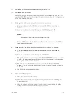
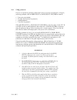
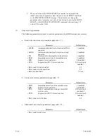
b.  Format parameter (page code = 3) 


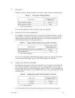
Specify the number of spare sectors for each cell in the "alternate sectors/zone" field.  It is 
recommended not to specify values smaller than the HDD default value in this field. 

 
(2) 

FORMAT UNIT command 


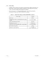
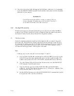
Initialize entire recording surface of the disk with the FORMAT UNIT command.  The FORMAT 
UNIT command initializes entire surface of the disk using the P lists, verifies data blocks after 
initialization, and allocates an alternate block for a defect block detected with verification.  With 
initialization, the value "00" is written into all bytes of all logical data blocks.  Only the position 
information of defect blocks detected with verification is registered in the G list.  The 
specifications are as follows: 


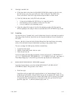
a. Specifying 

CDB 


Specify 0 for the "FmtData" bit and the "CmpLst" bit on CDB, 000 for the "Defect List 
Format" field, and data pattern written into the data block at initialization for the "initializing 
data pattern" field. 


b. Format 

parameter 


When the values in step a. are specified with CDB, the format parameter is not needed. 


Summary of Contents for MAX3036NC

Page 1: ...C141 E229 01EN MAX3147NC NP MAX3073NC NP MAX3036NC NP HARD DISK DRIVES PRODUCT MAINTENANCE MANUAL ...

Page 2: ... for incidental or consequential damages arising therefrom FUJTSU DISCLAIMS ALL WARRANTIES REGARDING THE INFORMATION CONTAINED HEREIN WHETHER EXPRESSED IMPLIED OR STATUTORY FUJITSU reserves the right to make changes to any products described herein without further notice and without obligation This product is designed and manufactured for use in standard applications such as office work personal d...

Page 3: ...C141 E229 i REVISION RECORD Edition Date published Revised contents 01 June 2005 Specification No C141 E229 EN ...

Page 4: ... T10 1236D Rev 20 NCITS 351 2001 SCSI Primary Commands 2 SPC 2 T10 996D Rev 8c NCITS 306 1998 SCSI 3 Block Commands SBC T10 1157D Rev 24 SCSI Architecture Model 2 SAM 2 T10 1365D Rev 10 SCSI Parallel Interface 4 SPI 4 1 ANSI American National Standard Institute In case of conflict between this manual and any referenced document this manual takes precedence ...

Page 5: ...ent CHAPTER 3 DATA FORMAT This chapter describes the data structure of the disk the address method and what to do about media defects CHAPTER 4 INSTALLATION REQUIREMENTS This chapter describes the basic physical and electrical requirements for installing the disk drives CHAPTER 5 INSTALLATION This chapter explains how to install the disk drives It includes the notice and procedures for setting dev...

Page 6: ... minor or moderate personal injury may occur if the user does not perform the procedure correctly IMPORTANT This indicates information that the helps the user use the product more effectively In the text the alert signal is centered followed below by the indented message A wider line space precedes and follows the alert message to show where the alert message begins and ends The following is an ex...

Page 7: ... performed However if error byte exceeds its allowable number correction may not be performed properly 2 5 Installation Damage Never remove any labels from the drive or deface them in any way 4 4 Hot temperature To prevent injury never touch the drive while it is hot The DE and LSI become hot during operation and remain hot immediately after turning off the power 5 1 Data loss 1 The user must not ...

Page 8: ... 6 4 Diagnostics and Maintenance Caution 1 To avoid shocks turn off the power before connecting or disconnecting a cable connector or plug 2 To avoid injury do not touch the mechanical assembly during disk drive operation 3 Do not use solvents to clean the disk drive Caution 1 Always ground yourself with a wrist strap connected to ground before handling ESD Electrostatics Discharge may cause the d...

Page 9: ...rements 5 Installation 6 Diagnostics and Maintenance 7 Error Analysis SCSI PHYSICAL INTERFACE SPECIFICATIONS 1 SCSI BUS 2 SCSI MESSAGE 3 ERROR RECOVERY SCSI LOGICAL INTERFACE SPECIFICATIONS 1 Command Processing 2 Data Buffer Management 3 Command Specifications 4 Parameter Data Formats 5 Sense Data and Error Recovery Method 6 Disk Media Management ...

Page 10: ...This page is intentionally left blank ...

Page 11: ...7 CHAPTER 3 DATA FORMAT 3 1 3 1 Data Space 3 1 3 1 1 Cylinder configuration 3 1 3 1 2 Alternate spare area 3 3 3 1 3 Track format 3 5 3 1 4 Sector format 3 6 3 1 5 Format capacity 3 8 3 2 Logical Data Block Addressing 3 8 3 3 Defect Management 3 10 3 3 1 Defect list 3 10 3 3 2 Alternate block allocation 3 10 CHAPTER 4 INSTALLATION REQUIREMENTS 4 1 4 1 Mounting Requirements 4 1 4 1 1 External dimen...

Page 12: ...es 5 12 5 6 Confirming Operations after Installation and Preparation for Use 5 13 5 6 1 Confirming initial operations 5 13 5 6 2 Checking SCSI connection 5 14 5 6 3 Formatting 5 17 5 6 4 Setting parameters 5 19 5 7 Dismounting Drives 5 23 5 8 Spare Disk Drive 5 23 CHAPTER 6 DIAGNOSTICS AND MAINTENANCE 6 1 6 1 Diagnostics 6 1 6 1 1 Self diagnostics 6 1 6 1 2 Test programs 6 4 6 2 Maintenance Inform...

Page 13: ... key additional sense code and additional sense code qualifier 7 1 7 2 Sense Data Analysis 7 3 7 2 1 Error information indicated with sense data 7 3 7 2 2 Sense data 3 0C 03 4 40 xx and 4 C4 xx 7 4 7 2 3 Sense data 1 1x xx 3 1x xx and E 1D 00 Disk read error 7 4 7 2 4 Sense data 4 44 xx 5 2x xx 5 3D 00 5 90 00 B 44 xx B 47 xx B 48 00 B 49 00 B 4D xx and B 4E 00 SCSI interface error 7 4 APPENDIX A ...

Page 14: ...ounting frame structure 4 5 Figure 4 5 Limitation of side mounting 4 6 Figure 4 6 Surface temperature measurement points 4 7 Figure 4 7 Service clearance area 4 7 Figure 4 8 Spin up current waveform 12V DC 4 8 Figure 4 9 Power on off sequence 1 4 8 Figure 4 10 Power on off sequence 2 4 9 Figure 4 11 Power on off sequence 3 4 9 Figure 4 12 AC noise filter recommended 4 11 Figure 4 13 NC connectors ...

Page 15: ...connections 5 4 Figure 5 2 Setting terminals location on NP models only 5 5 Figure 5 3 CN2 setting terminal on NP models only 5 6 Figure 5 4 Checking the SCSI connection A 5 15 Figure 5 5 Checking the SCSI connection B 5 16 Figure 6 1 Revision label example 6 9 Figure 6 2 Indicating revision numbers 6 10 Figure 6 3 Test flowchart 6 11 Figure 7 1 Format of extended sense data 7 2 ...

Page 16: ...ng 5 8 Table 5 4 Write protect setting NP model 5 9 Table 5 5 Setting of the SCSI interface operation mode NP model 5 9 Table 5 6 Setting the bus width of the SCSI interface NP model 5 9 Table 5 7 Default mode settings by CHANGE DEFINITION command 5 10 Table 5 8 Setting check list NP model only 5 11 Table 6 1 Self diagnostic functions 6 1 Table 6 2 System level field troubleshooting 6 14 Table 6 3...

Page 17: ...all Computer System Interface SCSI as described in the ANSI SCSI SPI 4 T10 1365D Rev 10 to the extent described in this manual The flexibility and expandability of the SCSI as well as the powerful command set of the HDD allow the user to construct a high performance reliable disk subsystem with large storage capacity The data format can be changed from the format at factory shipment by reinitializ...

Page 18: ... to the restrictions already established by End of Life Vehicle ELV Directive or by the national environmental laws of the EU member nations 3 SCSI standard The HDD provides not only SCSI basic functions but also the following features Arbitration Disconnection Reconnection Data bus parity The SCSI commands can manipulate data through logical block addressing regardless of the physical characteris...

Page 19: ...m continuous read write operation when processing data blocks on several tracks or cylinder 7 Multi segment data buffer The data buffer is 8M bytes Data is transferred between SCSI bus and disk media through this data buffer This feature provides the suitable usage environment for users Since the initiator can control the disconnect reconnect timing on the SCSI bus by specifying the condition of s...

Page 20: ... disk drive using its powerful retry processing If a recoverable data check occurs error free data can be transferred to the initiator after being corrected in the data buffer The initiator software is released from the complicated error recover processing by these error recovery functions of the HDD 12 Automatic alternate block reassignment If a defective data block is detected during read or wri...

Page 21: ...stem with large capacity can be constructed in the good space efficiency 17 Start Stop of spindle motor Using the SCSI command the host system can start and stop the spindle motor 18 Diagnosis The HDD has a diagnostic capability which checks internal controller functions and drive operations to facilitate testing and repair 19 Low power consumption By using highly integrated LSI components the pow...

Page 22: ... 1 1 and 1 2 The HDD is composed of disks heads spindle motor and disk enclosure DE with actuator and air circulation filter as well as the printed circuit assembly PCA with controller and read write pre amp Figure 1 1 NC model drives outer view Figure 1 2 NP model drives outer view ...

Page 23: ...rculation filter breather filter The disk enclosure DE configures a clean room to keep out particle and other contaminants The DE has a closed loop air recirculation system Using the movement of the rotating disks air is continuously cycled through a filter This filter will trap any particle floating inside the enclosure and keep the air inside the DE contaminant free To prevent negative pressure ...

Page 24: ...ystem configuration The HDDs are connected to the SCSI bus of host systems and are always operated as target The HDDs perform input output operation as specified by SCSI devices which operate as initiator SCSI bus 14 15 HDD HDD HDD Figure 1 3 System configuration ...

Page 25: ...essing of peripheral device Each SCSI device on the bus has its own unique address SCSI ID n in Figure 1 3 For input output operation a peripheral device attached to the SCSI bus that operates as target is addressed in unit called as logical unit A unique address LUN logical unit number is assigned for each logical unit The initiator selects one SCSI device by specifying that SCSI ID then specifie...

Page 26: ...This page is intentionally left blank ...

Page 27: ...ies and interface connector type when shipped Table 2 1 lists the model name and order number The data format can be changed by reinitializing with the user s system Table 2 1 Model names and order numbers Model name Order number SCSI type Capacity user area MAX3147NC CA06560 B400 SCA2 LVD MAX3147NP CA06560 B460 68 pin LVD 147 0GB MAX3073NC CA06560 B200 SCA2 LVD MAX3073NP CA06560 B260 68 pin LVD 7...

Page 28: ...Recording mode 32 34 MEEPRML External dimensions Height Width Depth 25 4 mm 101 6 mm 146 0 mm Weight 0 8 kg max Power consumption 5 11 5 W typ Fast 5 SCSI Cable length 6 m max Fast 10 SCSI Cable length 3 m max Single Ended Fast 20 SCSI Cable length 3 m max 6 Cable length 1 5 m max 7 Inter face LVD Ultra 2 Wide U160 U320 Cable length 25 m max 8 Cable length 12 m max 9 Areal density 58 Gbits inch2 D...

Page 29: ... HDD is ready and the stop time is the time for disks to completely stop from power off or stop command 5 This value indicates during idle mode Power supply at nominal voltage 1 25 C ambient 6 Up to 4 SCSI devices having capacitance of 25pF or less can use cable length of up to 3 0 m 7 5 to 8 SCSI devices having capacitance of 25pF or less can use cable length of up to 1 5 m 8 1 on 1 connection ca...

Page 30: ... 20 Hz 49m s2 5 G 20 to 300 Hz or less Vibration 2 Transport packaged 3 1 mm 5 to 20 Hz 49m s2 5 G 20 to 300 Hz or less Operating 637 4 m s2 65 G 2 ms duration Non operating 2451 7 m s2 250 G 2 ms duration Shock 2 Transport packaged 2451 7 m s2 250 G 2 ms duration Operating 305 to 3 048 m 1 000 to 10 000 feet Altitude Non operating 305 to 12 192 m 1 000 to 40 000 feet Idle 0 75 A ave Spin up 3 0 A...

Page 31: ... per 1016 bits read CAUTION Data loss The drive adopts Reed Solomon code for ECC The sector data is divided into 3 interleaving sectors and ECC is performed in each sector where the maximum number of errors up to 9 byte can be corrected Total maximum byte 9 byte 3 interleave 27 byte If the error of read sector keeps allowable error byte number correction is performed However if error byte exceeds ...

Page 32: ...tem cabinet so that the average DE surface temperature is as low as possible DE surface temperature 40 C or less 5 years DE surface temperature 41 C to 45 C 4 5 years DE surface temperature 46 C to 50 C 4 years DE surface temperature 51 C to 55 C 3 5 years DE surface temperature 56 C to 60 C 3 years DE surface temperature Exceeding 60 C Without warranty Keep the De surface temperature 60 C or less...

Page 33: ...ector Ο NC model Data bus parity Data bus CRC Ο Bus arbitration function Ο Disconnection reconnection function Ο SCSI ID 16 bit SCSI 0 to 15 Jumper selection NP model Addressing LUN logical unit number 0 fixed Data transfer Synchronous mode 2 8 bit SCSI Single ended type Ultra 2 type 16 bit SCSI Single ended type Ultra 2 Wide type U160 LVD type U320 LVD type Ο 20 MB s max Ο 40 MB s max Ο 40 MB s m...

Page 34: ...This page is intentionally left blank ...

Page 35: ...ta block addressing method described in Section 3 2 The internal test space is used by Read write test of self diagnostics test but user can t use direct access The system space is accessed inside the HDD at power on or during the execution of a specific command but the user cannot directly access the system space 3 1 1 Cylinder configuration The HDD allocates cylinders to the user space Internal ...

Page 36: ...to Cylinder 147 SA0 SA139 Internal test cylinder User Space for Cell 0 0 Spare Sectors per Cell 0 0 User Space for Cell 1 0 Spare Sectors per Cell 1 0 User Space for Cell P1 0 Spare Sectors per Cell P1 0 User Space for Cell xx 1 User Space for Cell yy 17 Zone Cell Cylinder 0 1 0 26 27 28 1 53 0 m 26 P1 m 1 1 17 n Figure 3 1 Cylinder configuration Apart from the above logical configuration the HDD ...

Page 37: ...n area for diagnostic purposes only and its data block length is always 512 bytes The Internal test space consists of 8 cylinders and outer most cylinder is always assigned Cylinder 147 to 154 The user cannot change the number of cylinders in the Internal test space or their positions 3 System space The system space is an area for exclusive use of the HDD itself and the following information are r...

Page 38: ...cylinders Figure 3 2 Spare area in cell An alternate cylinder is used when spare sectors in a cell are used up or 0 is specified as the number of spare sectors in a cell 1 cylinder at the end of each zone of the user space is allocated as alternate cylinders as shown in Figure 3 3 The user space and the system space share the alternate cylinders Zone Note The number of alternate cylinders cannot b...

Page 39: ...mat 2 Track skew and head skew To avoid waiting for one turn involved in head and cylinder switching the first logical data block in each track is shifted by the number of sectors track skew and head skew corresponding to the switching time Figure 3 5 shows how the data block is allocated in each track At the cylinder switching location in a head the first logical data block in track t 1 is alloca...

Page 40: ...the track skew factor and the head skew factor according to the specified logical data block length The value can be read out by the MODE SENSE or MODE SENSE EXTENDED command after the track has been formatted 3 1 4 Sector format Each sector on the track consists of an ID field a data field and a gap field which separates them Figure 3 6 gives sector format examples SCT PAD SM1 PLO Sync G1 SCT G2 ...

Page 41: ... data block which is specified with a parameter in the MODE SELECT command Any multiple of 4 between 512 and 528 bytes can be specified as the length 5 BCRC It is a 4 byte error detection code Errors in the ID field Single burst errors with lengths of up to 32 bits for each logical block can be detected 6 ECC This is the 54 byte code that allows detection and correction of errors in the data field...

Page 42: ... the maximum logical block address and the number of the logical data blocks can be read out by a READ CAPACITY MODE SENSE or MODE SENSE EXTENDED command after initializing the disk medium Table 3 1 Format capacity Model Data block length User blocks Format capacity GB MAX3147NC NP 287 277 984 147 0 MAX3073NC NP 143 638 992 73 5 MAX3036NC NP 512 71 819 496 36 7 1GB 1 000 000 000 bytes Note Total n...

Page 43: ...rding to steps 1 to 4 subsequent logical data blocks are assigned in ascending order of cell number in the same way as in steps 1 to 4 Logical data blocks are assigned starting from track 0 in the next cell until the last cylinder immediately preceding the alternate cylinder n 1 shown in Figure 3 1 of the zone except alternate cylinders in cells in the user space When the logical data block is all...

Page 44: ...tion information specified as the D list and information generated as the C list They are recorded in the system space on the disk drive The initiator can read out the contents of the P and G lists by the READ DEFECT DATA command 3 3 2 Alternate block allocation The alternate data block is allocated to a defective data block sectors in defective sector units by means of the defect management metho...

Page 45: ...ch are not physically consecutive to the adjacent logical data blocks If a command which processes several logical data blocks is specified the HDD processes those blocks in ascending order of logical data block 1 Alternate block allocation during FORMAT UNIT command execution When the FORMAT UNIT command is specified the allocation of the alternate block to those defective sectors included in the...

Page 46: ... are detected during FORMAT UNIT command the HDD allocates the alternate block s to the defective data blocks Reassign procedure itself is the same as one in REASSIGN BLOCKS command 1 Certification is permitted when DCRT flag is cleared DCRT flag 0 in FORMAT UNIT command The HDD checks all initialized logical data blocks by reading them out after the above alternate block allocation is made to ini...

Page 47: ...and Example Reassign Block 16 Unused spare sector Defective sector n represents a logical data block number Figure 3 8 Alternate block allocation by REASSIGN BLOCKS command 3 Automatic alternate block allocation Automatic alternate block allocation at read operation If the ARRE flag in the MODE SELECT parameter permits the automatic alternate block allocation the HDD automatically executes the alt...

Page 48: ...ble error log a Primary media check Creates an uncorrectable error pattern invalid LBA pattern in the position of the error LBA repeats the primary media check up to three times If the error still occurs after the check repeated three times it is judged to be defective Then it performs the alternate processing b Alternate processing Alternate media check Writes the data that causes an unrecoverabl...

Page 49: ...cification is disabled IMPORTANT Automatic alternate block allocation is made up to the following quantities during the execution of one command ARRE Twice AWRE Type 1 Eight times AWRE Type 2 Maximum number which can be processed within the recovery time limit If more than the above mentioned defective block is detected the alternate block assignment processing for the first defective block is exe...

Page 50: ...This page is intentionally left blank ...

Page 51: ...irements 4 3 Connection Requirements This chapter describes the environmental mounting power supply and connection requirements 4 1 Mounting Requirements 4 1 1 External dimensions Figures 4 1 and 4 2 show the external dimensions of the HDD and the locations of the holes for the HDD mounting screws ...

Page 52: ...4 2 C141 E229 The value marked with indicates the dimension between mounting holes on the bottom face Unit mm Figure 4 1 NC model dimensions ...

Page 53: ...C141 E229 4 3 The value marked with indicates the dimension between mounting holes on the bottom face Unit mm Figure 4 2 NP model dimensions ...

Page 54: ...d the tolerance of the angle is 5 from the horizontal plane a Horizontal 1 b Horizontal 2 c Vertical 1 d Vertical 2 e Upright mounting 1 Direction of gravity f Upright mounting 2 Figure 4 3 HDD orientations 4 1 3 Notes on mounting CAUTION Damage Never remove any labels from the drive or deface them in any way ...

Page 55: ...he corner must be 5 0 mm or less c Tightening torque of screw must be secured with 0 59N m 6kgf cm 12 d Impact caused by the electric screwdriver must be within the device specifications e Must be handled on an anti static mat Figure 4 4 Mounting frame structure 3 Limitation of side mounting Use the four screw holes at the both ends on the both sides as shown in Figure 4 5 Do not use the center ho...

Page 56: ...ent temperature measured 30 mm from the disk drive At designing the system cabinet consider following points Make a suitable air flow so that the DE surface temperature never exceed 60 C Cool the PCA side especially with air circulation inside the cabinet Confirm the cooling effect by measuring the surface temperature of specific ICs and the DE These measurement results must satisfy the temperatur...

Page 57: ...connection Surface P Setting terminal NP model only External operator panel connector Figure 4 7 Service clearance area 7 Environmental magnetic field Do not install the HDD in the vicinity of equipment giving off strong magnetic fields such as monitors televisions or loudspeakers 8 Leakage magnetic flux The HDD uses a high performance magnet to achieve a high speed seek Therefore a leak magnetic ...

Page 58: ...47NC NP MAX3073NC NP MAX3036NC NP Current 500mA div Time 2 sec div Current 500mA div Time 2 sec div Current 500mA div Time 2 sec div Figure 4 8 Spin up current waveform 12V DC 3 Power on off sequence a The order of the power on off sequence of 5V DC and 12V DC supplied to the HDD does not matter b In a system which uses the terminating resistor power supply signal TERMPWR on the SCSI bus the requi...

Page 59: ...C power on off sequence is as follows In a system with its all SCSI devices designed to prevent noise from leaking to the SCSI bus when power is turned on or off the power sequence does not matter if the requirement in b or c is satisfied In a system containing an SCSI device which is not designed to prevent noise from leaking to the SCSI bus the requirement given in Figure 4 11 must be satisfied ...

Page 60: ... motors should be started after a delay of 12 seconds times SCSI ID by setting CN1 38 pin to open and CN1 78 pin to short SCSI ID Delay time of spindle motor starting 0 1 2 15 0 12 s 24 s 180 s 5 Power supply to SCSI terminating resistor If power for the terminating resistor is supplied from the HDD to other SCSI devices through the SCSI bus the current carrying capacity of the 5 VDC power supply ...

Page 61: ...nection Requirements 4 3 1 SCA2 connector type 16 bit SCSI model NC model 1 Connectors Figure 4 13 shows the locations of connectors on the SCA2 connector type 16 bit SCSI model NC model SCSI connector CN1 including power supply Figure 4 13 NC connectors location ...

Page 62: ...ector Figure 4 14 shows the SCSI connector See Section B 1 in Appendix B for signal assignments on the connector For details on the physical electrical requirements of the interface signals refer to Sections 1 3 Physical Requirements and Section 1 4 Electrical Requirements of the SCSI Physical Interface Specifications Figure 4 14 SCA2 type 16 bit SCSI connector 3 Connector for external operator pa...

Page 63: ...nector CN1 Figure 4 15 NP connectors and terminals location 2 SCSI connector and power supply connector a 16 bit SCSI The connector for the SCSI bus is an unshielded P connector conforming to SCSI 3 type which has two 34 pin rows spaced 1 27 mm 0 05 inch apart Figure 4 16 shows the SCSI connector See Section B 2 in Appendix B for the signal assignments on the SCSI connector For details on the phys...

Page 64: ...minal fasten tab for DC grounding Therefore when connecting SG and FG in the system use the 5 VDC RETURN ground inside the power supply connector as the SG on the power supply side 4 Connector for external operator panel Connector for 16 bit SCSI external operator panel CN1 provides connector for the external operator panel other than the SCSI bus as shown in Figure 4 18 Also a connector for the e...

Page 65: ...ernal operator panel connector CN1 2 0mm 2 0mm Pin 24 Pin 23 Pin 2 Pin 1 Figure 4 19 External operator panel connector CN2 Pin Signal A1 ID0 A2 Fault LED A3 ID1 A4 ESID A5 ID2 A6 Reserved A7 ID3 A8 LED A9 N C A10 GND A11 5 V A12 WTP ...

Page 66: ...Input signals CN1 A1 A3 A5 A7 pin and CN2 02 04 06 08 pin These signals are used for providing switches to set the SCSI ID of the HDD externally Figure 4 20 shows the electrical requirements For the recommended circuit examples see Subsection 4 3 4 Figure 4 20 16 bit SCSI ID external input ...

Page 67: ...DD has been switched on it is possible to set up the SCSI ID by short circuiting CN1 A3 and CN1 A4 and CN1 A5 and CN1 A6 This pin gets high impedance status except above d LED and LED 5V Output signals CN1 A8 pin and CN2 21 22 pin These signals drive the external LED as same as LED on the front of the disk drive The electrical requirements are given in Figure 4 21 IMPORTANT 1 The external LED is i...

Page 68: ...41 E229 Figure 4 21 Output signal for external LED e WTP Input signal CN1 A12 and CN2 9 10 pin By connecting the CN1 A12 and CN2 10 pins to the GND writing operations into the HDD disk media are set to disable ...

Page 69: ...nts The requirements for cable connection between the HDD host system and power supply unit are given in Figure 4 22 Recommended components for connection are listed in Table 4 2 Figure 4 22 SCSI cables connection External operator panel example ...

Page 70: ...SE ELECTRIC Contact A3B 2630SCC HIROSE ELECTRIC External operator panel CN1 Cable AWG26 to 36 S3 Cable socket housing FCN 723J024 2M FUJITSU TAKAMIZAWA Contact FCN 723J G AM FUJITSU TAKAMIZAWA NP External operator panel CN2 Cable AWG28 S4 1 See Figure 4 22 1 SCSI cable Refer to Section 1 3 Physical Requirements and Section 1 4 Electrical Requirements of the SCSI Physical Interface Specifications 2...

Page 71: ...4 External operator panel on NP model drives only A recommended circuit of the external operator panel is shown in Figure 4 23 Since the external operator panel is not provided as an option this panel must be fabricated at the user site referring to the recommendation if necessary HDD C N 1 S3 A1 A3 A5 A7 A10 ID0 ID1 ID2 ID3 GND ID0 ID1 ID2 ID3 S3 A8 A11 LED 5V LED R Approx 300Ω 1 C N 2 S4 21 22 L...

Page 72: ...4 22 C141 E229 IMPORTANT Do not connect the external LED to both CN1 and CN2 Connect it to either of them ...

Page 73: ...cifications in Table 2 1 must be strictly observed 1 General notes a Do not give the drive shocks or vibrations exceeding the value defined in the specifications because it may cause critical damage to the drive Especially be careful when unpacking b Do not leave the drive in a dirty or contaminated environment c Since static discharge may destroy the CMOS semiconductors in the drive note the foll...

Page 74: ...ce and keep removed screws and other parts where they will not get lost or damaged d Keep a record of all maintenance work for replacing 4 Packaging a Store the drive in an antistatic case Fcell b It is recommended to use the same cushions and packages as those at delivery If those at delivery cannot be used use a package with shock absorption so that the drive is free from direct shocks In this c...

Page 75: ...SI up to 16 devices including the host adapter HDD and other SCSI devices can be connected to the SCSI bus in arbitrary combinations Install a terminating resistor on the SCSI device connected to both ends of the SCSI cable See Section 4 3 for the cable connection requirements and power cable connections 1 Connecting one HDD HDD ...

Page 76: ... C141 E229 2 Connecting more than one HDD single host HDD HDD Figure 5 1 SCSI bus connections 1 of 2 3 Connecting more than one HDD multi host SCSI terminator HDD HDD Figure 5 1 SCSI bus connections 2 of 2 ...

Page 77: ...del because the setting terminal is included in SCSI connector CN1 CAUTION Data loss 1 The user must not change the setting of terminals not described in this section Do not change setting status set at factory shipment 2 Do not change the setting of terminals except following setting pins during the power is turned on Write protect Pin pair 9 10 of the CN2 setting terminal NP model only 3 To shor...

Page 78: ...5 2 and 5 3 IMPORTANT When the SCSI ID is set using the external operator panel connector CN1 of NP model all pins listed in Table 5 1 should be open If any of pins are shorted unexpected SCSI ID is set 24 22 20 18 16 14 12 10 8 6 4 2 23 21 19 17 15 13 11 9 7 5 3 1 Terminator power supply Supply LED signal HDD Reset signal N C Force Single Ended LVD mode Force Narrow 16 bit SCSI Motor start mode W...

Page 79: ...rt Open Short Open Short Open Short 11 Short Short Open Short Short Short Open Short 12 Open Open Short Short Open Open Short Short 13 Short Open Short Short Short Open Short Short 14 Open Short Short Short Open Short Short Short 15 1 Short Short Short Short Short Short Short Short 1 Set at factory shipment IMPORTANT 1 To set the setting terminals on NC models to short apply voltage ranging betwee...

Page 80: ...l 3 NP model Start timing of the spindle motor Pin 38 of CN1 RMT START Pin 78 of CN1 DYLD START Pin pair 11 12 of CN2 GND RMSTART Starting of the motor is controlled with the START STOP UNIT command Short Open or Short Open The motor is started immediately after the power supply is turned on or after the microcode is downloaded Open Open Short 1 The motor is started after the elapse of a delay tim...

Page 81: ...on mode Pin pair 15 16 of CN2 GND DIFFSENS Follows the DIFFSNS signal level on the SCSI bus Open 1 Single Ended mode Short 1 Set at factory shipment For NC model the function of the SCSI interface operation mode is not supported so the SCSI interface operation mode follows the level of the DIFFSNS signal on the SCSI bus 5 Setting the bus width of the SCSI interface By establishing a short circuit ...

Page 82: ...tion 3 1 4 CHANGE DEFINITION 40 of the SCSI Logical Interface Specifications for details of the CHANGE DEFINITION command Table 5 7 Default mode settings by CHANGE DEFINITION command Mode setting Contents SCSI level SCSI 3 SYNCHRONOUS DATA TRANSFER REQUEST message sending Not sent from HDD UNIT ATTENTION report mode Reported Reselection retry count Not restricted WIDE DATA TRANSFER REQUEST message...

Page 83: ...n below See Subsection 4 1 for the details of requirements for installing the HDD 1 With a system to which an external operator panel is mounted if it is difficult to access the connector after the drive is mounted on the system cabinet connect the external operator panel cable before mounting the drive 2 Fix the drive in the system cabinet with four mounting screws as follows The drive has 10 mou...

Page 84: ...rator panel if required for NP model c Connect the SCSI cable d Fix the cables so that they do not touch the DE and PCAs or so that the smooth flow of the cooling air in the system cabinet is assured CAUTION Damage 1 Be careful of the insertion orientations of the SCSI connectors With the system in which terminating resistor power is supplied via the SCSI cable if the power is turned on the overcu...

Page 85: ...n in the case of setting so that motor starts with START STOP command a When power is turned on the LED blinks an instant and the HDD executes initial self diagnosis b If an error is detected in the initial self diagnosis the LED blinks c The spindle motor does not start rotating until the START STOP UNIT command for the start is issued The initiator needs to issue the START STOP UNIT command to s...

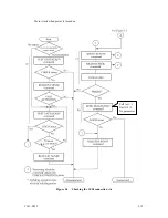
Page 86: ...de specified with setting terminal Figure 5 4 shows the recommended checking procedure for the mode that the motor starts when power is turned on Figure 5 5 shows for the mode that the motor starts by the START STOP command In these recommended checking procedures following items are checked Note Following steps a to d correspond to a to d in Figures 5 4 and 5 5 a Issue the TEST UNIT READY command...

Page 87: ...C141 E229 5 15 Motor starts when power is turned on Figure 5 4 Checking the SCSI connection A 60 Self test 1 Unit Of 1 No parameter d ...

Page 88: ...5 16 C141 E229 Motor starts by START STOP command Figure 5 5 Checking the SCSI connection B Executing time about 60 seconds ...

Page 89: ...ttributes different from the default format all recording surface of the disk must be formatted initialized according to the procedures below The user can change the following data attributes at initialization Logical data block length Number of logical data blocks in the user space Alternate spare area size This section outlines the formatting at installation Refer to Subsection 3 1 5 MODE SELECT...

Page 90: ...nitialization and allocates an alternate block for a defect block detected with verification With initialization the value 00 is written into all bytes of all logical data blocks Only the position information of defect blocks detected with verification is registered in the G list The specifications are as follows a Specifying CDB Specify 0 for the FmtData bit and the CmpLst bit on CDB 000 for the ...

Page 91: ...equirements specific to the user This section outlines the parameter setting procedures Refer to Subsection 3 1 5 MODE SELECT 15 and 3 1 6 MODE SELECT EXTENDED 55 of the SCSI Logical Interface Specifications for further details of the MODE SELECT and MODE SELECT EXTENDED commands and specifying the parameters IMPORTANT 1 At factory shipment of the HDD the saving operation for the MODE SELECT param...

Page 92: ...ration Automatic alternate block allocation at read operation Uncorrectable data transfer to the initiator Immediate correction of correctable error Report of recovered error Suppression of ECC error correction 1 enabled 1 enabled 1 enabled 1 enabled 0 disabled 0 Correction is enabled Retry count at read operation Retry count at write operation Recovery time limit 63 63 30 sec b Verify error recov...

Page 93: ...gement of the SCSI Logical Interface Specifications for further details Parameter Default value Buffer full ratio 00 HEX Buffer empty ratio 00 HEX Notes 1 In a system without the disconnection function these parameters need not be specified 2 Determine the parameter values in consideration of the following performance factors of the system Time required for reconnection processing Average data tra...

Page 94: ...enable Number of blocks for which prefetch is suppressed X FFFF Minimum prefetch X 0000 Maximum prefetch X XXXX 1 cache segment Number of blocks with maximum prefetch restrictions X FFFF Number of segments X 08 Notes 1 When Read Ahead caching operations are disabled by the caching parameter these parameter settings have no meaning except write cache feature 2 Determine the parameters in considerat...

Page 95: ...e general procedures and notes on dismounting the drive It is recommended before dismounting the drive to make sure the spindle motor completely stops after power was turned off a Remove the power cable b Remove the SCSI cable NC Model uses a single cable for power supply and the SCSI interface c When the external operator panel is mounted remove the cable If it is difficult to access the connecto...

Page 96: ...This page is intentionally left blank ...

Page 97: ... The HDD has the following self diagnostic function This function checks the basic operations of the HDD Initial self diagnostics Online self diagnostics SEND DIAGNOSTIC command Table 6 1 lists the contents of the tests performed with the self diagnostics For a general check of the HDD including the operations of the host system and interface use a test program that runs on the host system see Sub...

Page 98: ...l self diagnostics When power is turned on the HDD starts initial self diagnostics The initial self diagnostics checks the basic operations of the hardware functions If an error is detected in the initial self diagnostics the LED on the drive front panel blinks In this status the HDD posts the CHECK CONDITION status to all I O operation requests other than the REQUEST SENSE command When the CHECK ...

Page 99: ...fications 2 Online self diagnostics SEND DIAGNOSTIC command The initiator can make the HDD execute self diagnostics by issuing the SEND DIAGNOSTIC command The initiator specifies the execution of self diagnostics by setting 1 for the SelfTest bit on the CDB in the SEND DIAGNOSTIC command and specifies the test contents with the UnitOfl bit When the UnitOfl bit on the CDB is set to 0 the HDD execut...

Page 100: ...en if the error information sense data is read Only when the power is turned off or re turned on the status can be cleared When this status is cleared the HDD executes the initial self diagnostics again see item 1 Refer to Subsection 3 4 1 SEND DIAGNOSTIC 1D of the SCSI Logical Interface Specifications for further details of the command specifications CAUTION Data loss When the SEND DIAGNOSTIC com...

Page 101: ...ENDED or VERIFY command 4 Write read test By using a data block in the internal test space the write read test can be executed with an arbitrary pattern for a disk drive in which user data is stored 6 2 Maintenance Information 6 2 1 Precautions Take the following precautions to prevent injury during maintenance and troubleshooting CAUTION 1 To avoid shocks turn off the power before connecting or d...

Page 102: ...off before connecting or disconnecting a cable connector or plug 3 Do not remove a PCA 4 Do not use a conductive cleaner to clean a disk drive assembly 5 Ribbon cables are marked with a colored line Connect the ribbon cable to a cable connector with the colored wire connected to pin 1 6 2 2 Maintenance requirements 1 Preventive maintenance Preventive maintenance is not required 2 Service life See ...

Page 103: ...rmation must be included a HDD model part number P N revision number serial number S N and date of manufacturing b Error status Date when the error occurred System configuration Environmental conditions temperature humidity and voltage c Error history d Error contents Outline of inconvenience Issued commands and specified parameters Sense data Other error analysis information CAUTION Data loss Sav...

Page 104: ...evels 1 Field maintenance disk drive replacement This replacement is done at the user s site Replacement uses standard tools Replacement is usually done by the user retail dealer distributor or OEM engineer 2 Factory maintenance parts replacement This replacement can only be done by Fujitsu Replacement includes maintenance training and OEM engineer support OEM engineers usually support retail deal...

Page 105: ...t factory shipment When the disk drive is shipped from the factory the revision number is indicated by deleting numbers in the corresponding letter line up to the corresponding number with see Figure 6 2 2 Changing revision number in the field To change the revision number because parts are replaced or other modification is applied in the field the new level is indicated by enclosing the correspon...

Page 106: ...shipment Revising at field Rev A2 Rev A3 Figure 6 2 Indicating revision numbers 6 2 5 Tools and test equipment Disk drive troubleshooting and repair in the field require only standard SCSI tools No special tools or test equipment are required This manual does not describe the factory level tools and test equipment 6 2 6 Tests This disk drive can be tested in the following ways Initial seek operati...

Page 107: ...Continue operation Check host system Table 6 2 Host system normal Analyze system related error Replaced or repair disk drive Disk drive normal Execute diagnostic test using a host computer or test equipment Test results OK Test using voltage or temperature stress Test results OK Normal Analyze disk drive error Table 6 3 Yes Yes No No Yes No Yes No Figure 6 3 Test flowchart ...

Page 108: ... the disk drive an interrupt occurs The interrupt is posted to the MCU on the PCA The MCU stops the currently processed command and causes the CHECK CONDITION status to post the error to the initiator When receiving the CHECK CONDITION status the initiator issues a REQUEST SENSE command to collect detailed information about the error The initiator then issues a REZERO UNIT command to return the re...

Page 109: ...ar e g abnormal noise in disk enclosure or burning of the PCA troubleshooting is straightforward 6 4 2 Troubleshooting with disk drive replacement in the field At this level of maintenance we recommend replacing the disk drive as a unit If replacing the disk drive rectifies the fault return the removed disk drive to the factory for test and repair If the newly installed disk drive does not rectify...

Page 110: ...resistors For a daisy chain connection check the terminating resistor on the last disk drive only For a star burst connection check that the terminating resistor is correctly mounted on all disk drives Drive selection address Check that the disk SCSI ID is set correctly Plug setup Check that the jumpers on the PCA are set so that the disk drive and host computer operate normally See Section 5 3 Sy...

Page 111: ...Disk drive troubleshooting Item Recommended action Frequent or repeated seek errors Collect sense data and see Chapter 7 Replace the disk drive and check that the test method is correct If the error recurs it is likely that the disk drive is normal but the test method is incorrect Intermittent or nonfatal errors Replace the disk drive and check that the test method is correct If the error recurs i...

Page 112: ...he factory This manual does not cover troubleshooting at the factory level 6 4 5 Finding possibly faulty parts Finding possibly faulty parts in the field was explained in Subsection 6 4 2 This manual does not cover finding possibly faulty parts at the factory level ...

Page 113: ...ata When HDD posts a CHECK CONDITION status or detects a fatal error in the SCSI bus the current command or queued command is cleared In such a case the HDD generates sense data about the command issuing initiator The initiator can read the sense data by issuing a REQUEST SENSE command Even if a transfer byte length that is shorter than the sense data length of the tested device is specified the c...

Page 114: ...7 X 28 additional sense data length 8 9 10 11 12 Additional sense code 13 Additional sense code qualifier 14 X 00 15 SKSV 16 Sense key specific information 17 18 X 0 0 0 SCSI ID 19 CDB operation code 20 47 Figure 7 1 Format of extended sense data Detail information LSB LSB Command specific information Information Basic information MSB ...

Page 115: ...c An error occurred in power on self diagnosis A drive error occurred 1 3 1x 1x xx xx A disk read error occurred A disk read error occurred E 1D 00 Data discrepancy found by VERIFY command byte check 5 2x 3D 90 xx 00 00 An SCSI error such as an invalid operation code occurred The Reserve bit of the IDENTIFY message was set to 1 The RESERVE or RELEASE command cannot be executed because the SCSI ID ...

Page 116: ...In this case assign an alternate block to the error detected block using a REASSIGN BLOCKS command For an explanation of the REASSIGN BLOCKS command refer to Subsection 3 3 2 REASSIGN BLOCKS 07 of the SCSI Logical Interface Specifications If this error occurs in different blocks the PCA or the DE is faulty 7 2 4 Sense data 4 44 xx 5 2x xx 5 3D 00 5 90 00 B 44 xx B 47 xx B 48 00 B 49 00 B 4D xx and...

Page 117: ...C141 E229 A 1 APPENDIX A SETTING TERMINALS A 1 Setting Terminals on NP model only This appendix describes setting terminals ...

Page 118: ... only Open Short Open Short SCSI ID 10 16 bit SCSI only Short Short Open Short SCSI ID 11 16 bit SCSI only Open Open Short Short SCSI ID 12 16 bit SCSI only Short Open Short Short SCSI ID 13 16 bit SCSI only Open Short Short Short SCSI ID 14 16 bit SCSI only SCSI ID Short Short Short Short SCSI ID 15 16 bit SCSI only Open Write operation is enabled Write protect Short Write operation is disabled P...

Page 119: ...ENDIX B CONNECTOR SIGNALALLOCATION B 1 SCSI Connector Signal Allocation SCA2 type LVD 16 bit SCSI B 2 SCSI Connector Signal Allocation 68 pin type LVD 16 bit SCSI This appendix describes the connector signal allocation ...

Page 120: ...9 DB09 DB09 49 10 DB08 DB08 50 11 I O I O 51 12 REQ REQ 52 13 C D C D 53 14 SEL SEL 54 15 MSG MSG 55 16 RST RST 56 17 ACK ACK 57 18 BSY BSY 58 19 ATN ATN 59 20 P_CRCA P_CRCA 60 21 DB07 DB07 61 22 DB06 DB06 62 23 DB05 DB05 63 24 DB04 DB04 64 25 DB03 DB03 65 26 DB02 DB02 66 27 DB01 DB01 67 28 DB00 DB00 68 29 DBP1 DBP1 69 30 DB15 DB15 70 31 DB14 DB14 71 32 DB13 DB13 72 33 DB12 DB12 73 34 5V 5V RETURN...

Page 121: ...08 DB02 DB02 42 09 DB03 DB03 43 10 DB04 DB04 44 11 DB05 DB05 45 12 DB06 DB06 46 13 DB07 DB07 47 14 P_CRCA P_CRCA 48 15 GND GND 49 16 DIFFSNS GND 50 17 TERMPWR TERMPWR 51 18 TERMPWR TERMPWR 52 19 Reserved Reserved 53 20 GND GND 54 21 ATN ATN 55 22 GND GND 56 23 BSY BSY 57 24 ACK ACK 58 25 RST RST 59 26 MSG MSG 60 27 SEL SEL 61 28 C D C D 62 29 REQ REQ 63 30 I O I O 64 31 DB08 DB08 65 32 DB09 DB09 6...

Page 122: ...This page is intentionally left blank ...

Page 123: ...euing feature 1 4 compactness 1 2 confirming initial operation 5 13 confirming operation after installation and preparation for use 5 13 connecting cable 5 12 connection 5 3 connector signal allocation B 1 continuous block processing 1 3 control mode parameter 5 22 controller circuit 1 7 current waveform 4 8 cylinder configuration 3 2 D data format 3 1 data space 3 1 default mode setting by CHANGE...

Page 124: ...5 17 mode setting 5 10 motor start mode 5 8 motor start mode setting 5 8 mounting 4 4 mounting drive 5 11 mounting frame structure 4 5 mounting procedure 5 11 mounting requirement 4 1 mounting screw 4 5 multi segment data buffer 1 3 N NC connector location 4 11 NC model dimension 4 2 NC model drive outer view 1 6 note on handling drive 5 1 NP connector and terminal location 4 13 NP model dimension...

Page 125: ... only 5 11 setting of SCSI interface operation mode 5 9 setting parameter 5 19 setting SCSI terminator power supply 5 8 setting terminal 5 5 A 1 setting terminal on NP model only A 2 setting terminal location 5 5 setting terminator power supply 5 8 spare area in cell 3 4 spare disk drive 5 23 specification 2 1 spindle motor 1 7 standard feature 1 2 START STOP command 5 13 start stop of spindle mot...

Page 126: ...This page is intentionally left blank ...

Page 127: ...nt G Good F Fair P Poor General appearance Technical level Organization Clarity Accuracy Illustration Glossary Acronyms Abbreviations Index Comments Suggestions List any errors or suggestions for improvement Page Line Contents Please send this form to the address below We will use your comments in planning future editions Address Fujitsu Learning Media Limited 37 10 Nishikamata 7 chome Oota ku Tok...

Page 128: ...This page is intentionally left blankw ...

Page 129: ......

Page 130: ......

Reviews: