Trigger-Input and Emulator-Output
FR Family MB2198-01 Emulating and Debugging Installation Guide, Doc. No. 002-05223 Rev. *A
28
9.2
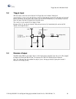
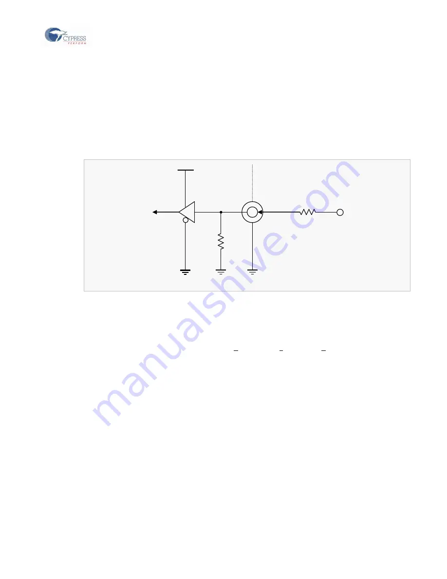
Trigger-Input
With this input an execution can be stopped. The Trigger-
Input is a hardware “break point”.
A logical “high” (= 3.3V) on this input stops the execution in the debugging mode. Note, that because of internal
latches and different clock speeds of the emulator and the MCU the termination is not immediately. The break
slip is in a range of dozens to hundreds machine clock cycles.
The execution can be resumed after a triggered break.
Because of the 3.3V input and an internal 100K pull down resistor, it is recommended to use a serial 50K
resistor, if a 5V signal is used:
9.3
Emulator-Output
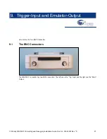
The BNC-
Output “EMUL” goes logical “high” (= 3.3V) if a program is executed and is “low” (= 0V) if the program
is stopped or a break point has occurred. This signal can be used for controlling external hardware.
Note: The TRIG input has to be enabled for using at:
Setup > Debug environment> Debug Environment >
Emulation: TRIG Input: enable
3.3V
To internal
emulator circuit
100K
50K
TTL-Output (5V)
TRIG
(BNC)
Internal external
Summary of Contents for MB2147-01
Page 10: ......
Page 11: ...FUJITSU LIMITED DSU FR EMULATOR MB2198 01 HARDWARE MANUAL ...
Page 12: ......
Page 20: ...viii ...
Page 22: ...x ...
Page 56: ...34 CHAPTER 2 CONNECTION METHOD ...
Page 64: ...42 CHAPTER 3 OPERATION METHOD ...
Page 66: ......
Page 76: ...54 APPENDIX B User System Specifications ...
Page 78: ......
Page 92: ......


