


3
1.2 Appearance and Part Names
1.2
Appearance and Part Names
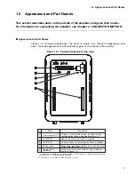
This section describes parts on the outside of the emulator and gives their names.
For information on connecting the emulator, see Chapter 2 "CONNECTION METHOD".
■
Appearance and Part Names
Figure 1.2-1 "Emulator Appearance (top view)" to Figure 1.2-3 "Emulator Appearance (rear
view)" show the appearance and have names of parts on the outside of the emulator.
Figure 1.2-1 Emulator Appearance (top view)
No.
Name
Description
Status indicator LCD
Displays a variety of information, including settings,
communication status, and operation status.(*1)
Goes on when emulator power is supplied.
POWER LED
UVCC LED
Goes on when user system power (UVcc) is supplied.
Setting switch
Used to change settings and the information displayed
on the status indicator LCD. (*1)
Adapter board
connector
Accepts the connection of different types of adapter
boards (options). (*2)
*1 For explanations of displays of the status indicator LED and how to operate the setting switch,
see Section 3.1, "Operating Setting Switches."
*2 This connector is not used if a DSU-FR cable is used.
4
5
1
2
3
Summary of Contents for MB2147-01
Page 10: ......
Page 11: ...FUJITSU LIMITED DSU FR EMULATOR MB2198 01 HARDWARE MANUAL ...
Page 12: ......
Page 20: ...viii ...
Page 22: ...x ...
Page 56: ...34 CHAPTER 2 CONNECTION METHOD ...
Page 64: ...42 CHAPTER 3 OPERATION METHOD ...
Page 66: ......
Page 76: ...54 APPENDIX B User System Specifications ...
Page 78: ......
Page 92: ......


