
4
CHAPTER 1 PRODUCT HANDLING AND SPECIFICATIONS
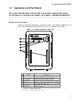
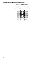
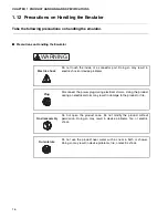
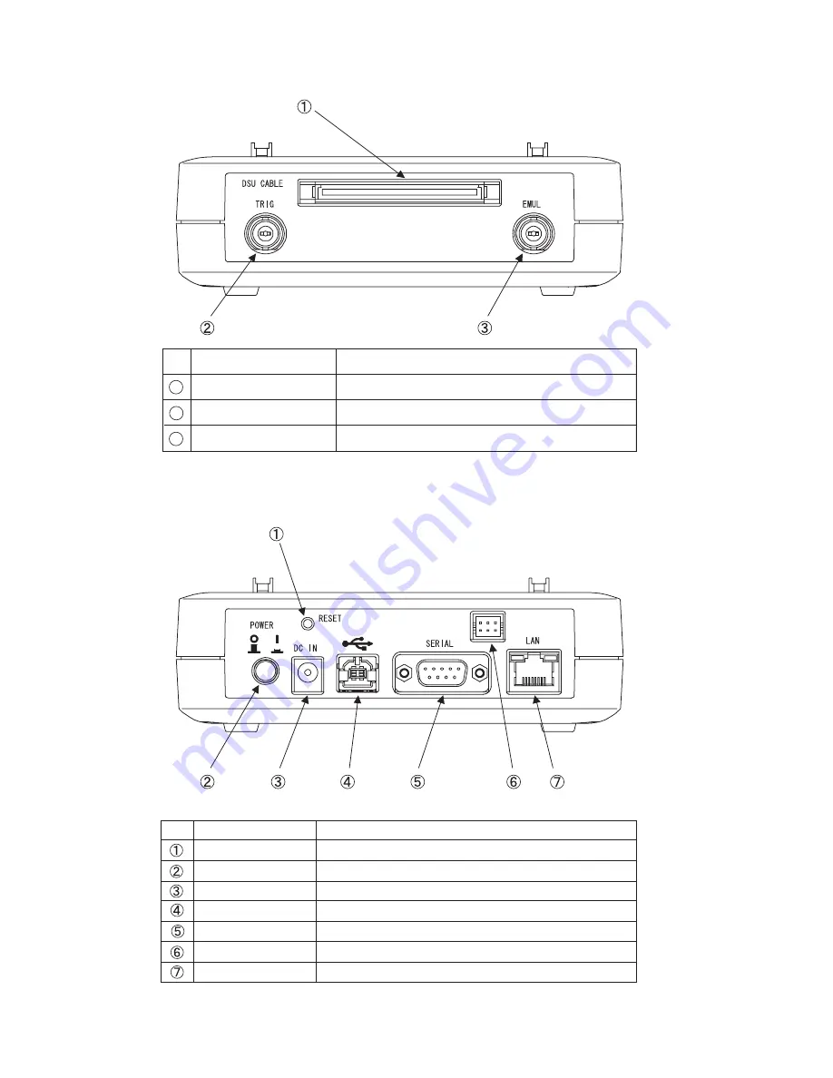
Figure 1.2-2 Emulator Appearance (front view)
Figure 1.2-3 Emulator Appearance (rear view)
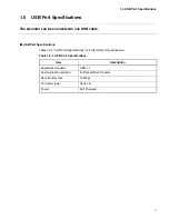
No.
Name
Description
DSU-FR cable connector Connector for a DSU-FR cable
1
2
3
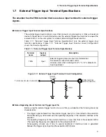
TRIG terminal
Terminal used for input of external trigger signals
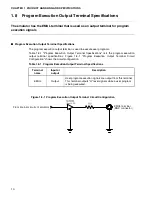
EMUL terminal
Terminal that outputs program execution signals
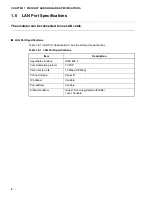
No.
Name
Description
Reset switch
Reset switch for the emulator system
Power switch
Power switch for the emulator
DC inlet
Inlet in which to plug the AC adapter
USB connector
Connector for a USB cable
RS-232C connector
Connector for a RS-232C cable
TEST terminal
Terminal for testing the product. Do not use this terminal.
LAN connector
Connector for a LAN cable
Summary of Contents for MB2147-01
Page 10: ......
Page 11: ...FUJITSU LIMITED DSU FR EMULATOR MB2198 01 HARDWARE MANUAL ...
Page 12: ......
Page 20: ...viii ...
Page 22: ...x ...
Page 56: ...34 CHAPTER 2 CONNECTION METHOD ...
Page 64: ...42 CHAPTER 3 OPERATION METHOD ...
Page 66: ......
Page 76: ...54 APPENDIX B User System Specifications ...
Page 78: ......
Page 92: ......