


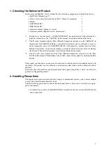
48
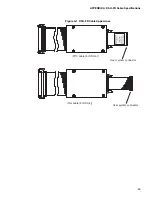
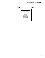
APPENDIX A DSU-FR Cable Specifications
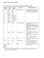
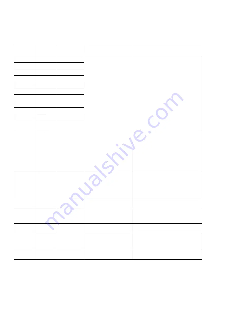
Table A-3 Emulator Interface Signal Line Terminal Arrangement (connector for DSU-4 )
Terminal
number
Terminal
name
Input or output
Description
Connection conditions
20
ICLK
Input
Emulator control
•
Connected to the terminal with the same
name on the evaluation MCU.
•
Has a maximum wiring length of 50 mm.
18
ICS[0]
Input
17
ICS[1]
Input
16
ICS[2]
Input
14
ICD[0]
Input/Output
13
ICD[1]
Input/Output
12
ICD[2]
Input/Output
11
ICD[3]
Input/Output
10
BREAK
Output
5
TRST
Output
8
PLEVEL
(*1)
Output
7
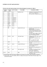
INIT
Output
Evaluation MCU reset
•
Connected to the reset terminal of the
evaluation MCU.
•
The reset output circuit of the user
system and the evaluation MCU reset
terminal must be isolated during use of
the emulator.
•
Open drain output. Includes a 10k
Ω
pull-
up resistor using the UV
CC
terminal.
(V
OL
= +0.4 V max, I
OL
=12 mA)
6
xRSTIN
Input
User system reset
•
Connected to the reset output circuit of
the user system.
•
Enabled when "L" level signals are
input.
(V
IH
= +1.7 V min, I
IH
= -10
µ
A)
(V
IL
= +0.8 V max, I
IL
= 10
µ
A)
3
DSUIO
-
Spare
•
Must be left unconnected because it is
not used.
2
V
CC
T*1
Output
Dedicated DSU power
•
Connected to the terminal with the same
name on the evaluation MCU.
(+3.3 V / 350 mA)
1
N.C
-
-
•
Must be left unconnected because it is
not used.
4
UV
CC
Input
User system power
•
Connected to the external I/O power
supply of the evaluation MCU.
(0 V to +5.5 V / 100 mA or less)
9,15,19
GND
-
GND
•
Connected to the V
SS
terminal (0 V) of
the evaluation MCU.
*1: Some evaluation MCUs do not have a PLEVEL or V
CC
T terminal. In such cases, leave the terminal unconnected.
*2: Connect to the V
CC
pin if the evaluation MCU has a single power supply and to the external I/O power supply if it has
multiple power supplies.
Summary of Contents for MB2147-01
Page 10: ......
Page 11: ...FUJITSU LIMITED DSU FR EMULATOR MB2198 01 HARDWARE MANUAL ...
Page 12: ......
Page 20: ...viii ...
Page 22: ...x ...
Page 56: ...34 CHAPTER 2 CONNECTION METHOD ...
Page 64: ...42 CHAPTER 3 OPERATION METHOD ...
Page 66: ......
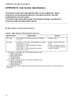
Page 76: ...54 APPENDIX B User System Specifications ...
Page 78: ......
Page 92: ......


