


51
APPENDIX B User System Specifications
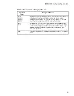
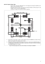
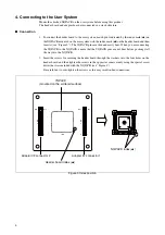
■
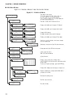
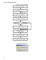
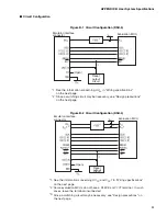
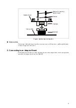
Circuit Configuration
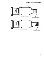
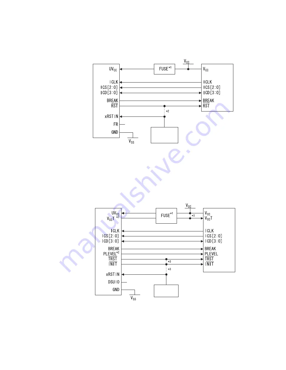
Figure B-1 Circuit Configuration (DSU-3)
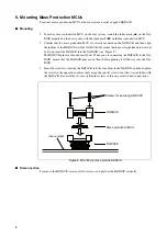
Figure B-2 Circuit Configuration (DSU-4)
Emulator interface
connector
Evaluation MCU
(Open)
Reset
output
circuit
*1: See the information concerning UV
CC
in "Wiring specifications"
on the next page.
Since a switching circuit may be necessary, see "Design precautions"
on the next page.
*2:
Emulator interface
connector
Evaluation MCU
(Open)
Reset
output
circuit
See the information concerning UV
CC
and V
CC
T in "Wiring specifications"
on the next page.
Some evaluation MCUs do not have a PLEVEL or V
CC
T terminal. In such
cases, leave the terminal unconnected.
Since a switching circuit may be necessary, see "Design precautions" on
the next page.
*1:
*2:
*3:
Summary of Contents for MB2147-01
Page 10: ......
Page 11: ...FUJITSU LIMITED DSU FR EMULATOR MB2198 01 HARDWARE MANUAL ...
Page 12: ......
Page 20: ...viii ...
Page 22: ...x ...
Page 56: ...34 CHAPTER 2 CONNECTION METHOD ...
Page 64: ...42 CHAPTER 3 OPERATION METHOD ...
Page 66: ......
Page 76: ...54 APPENDIX B User System Specifications ...
Page 78: ......
Page 92: ......