


52
APPENDIX B User System Specifications
■
Design Precautions
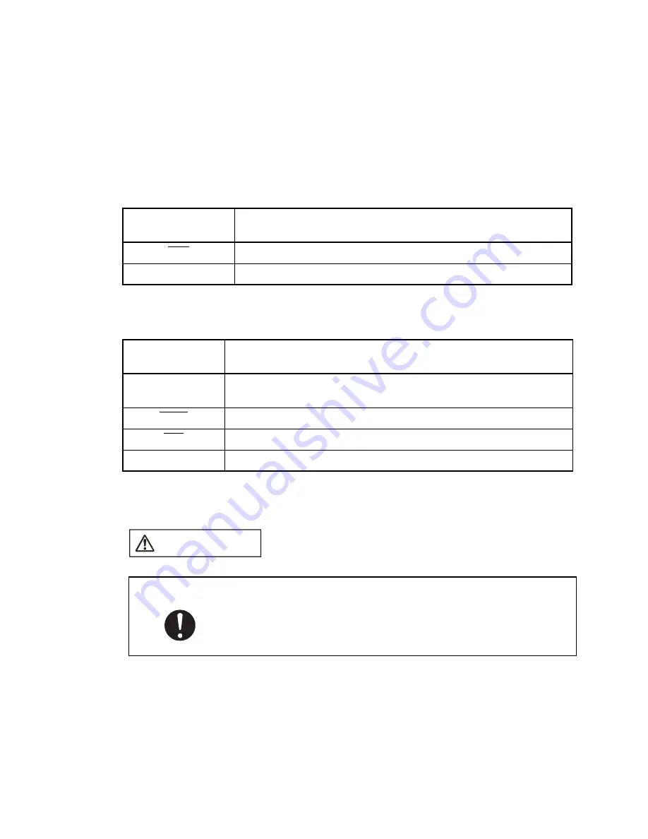
To operate the evaluation MCU on the user system without connecting the emulator, you must
adequately terminate the input terminals of the evaluation MCU that are connected to the
emulator interface on the user system.
A switching circuit may therefore be necessary on the user system. Be careful on this point
during the design process.
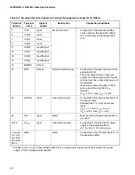
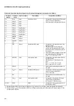
Table B-2 "Emulator Interface Terminal Termination (DSU-3)" and Table B-3 "Emulator Interface
Terminal Termination (DSU-4)" summarize the termination of emulator interface terminals.
■
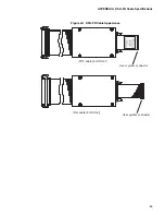
Wiring Specifications
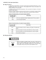
Table B-2 Emulator Interface Terminal Termination (DSU-3)
Evaluation MCU
terminal name
Termination
RST
Must be connected to the reset output terminal of the user system.
Other
Must be left unconnected.
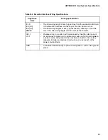
Table B-3 Emulator Interface Terminal Termination (DSU-4)
Evaluation MCU
terminal name
Termination
V
CC
T
Must be connected to the V
CC
terminal (+3V power) of the evaluation
MCU.
TRST
Must be connected to the reset output terminal of the user system.
INIT
Must be connected to the reset output terminal of the user system.
Other
Must be left unconnected.
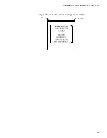
Because incorrectly connected probes may cause a short-circuit or
reverse connection between power supply and GND in operation, to
ensure safety, insert a protective circuit such as a fuse into power
supply pattern. Doing so may result in device problems or fire.
CAUTION
Attention
Summary of Contents for MB2147-01
Page 10: ......
Page 11: ...FUJITSU LIMITED DSU FR EMULATOR MB2198 01 HARDWARE MANUAL ...
Page 12: ......
Page 20: ...viii ...
Page 22: ...x ...
Page 56: ...34 CHAPTER 2 CONNECTION METHOD ...
Page 64: ...42 CHAPTER 3 OPERATION METHOD ...
Page 66: ......
Page 76: ...54 APPENDIX B User System Specifications ...
Page 78: ......
Page 92: ......


