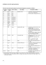


3
■
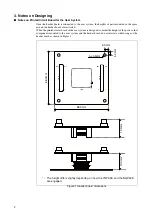
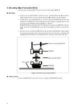
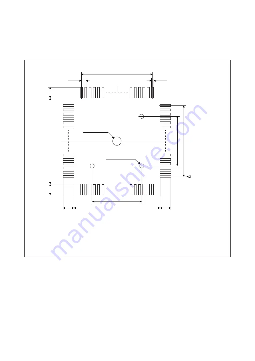
MCU Footprint Design Notes
Figure 2 shows the recommended dimensions of the footprint for mounting the NQPACK on the
printed circuit board of the user system.
The printed circuit board of the user system must be designed with due consideration given to this
footprint as well as to the mass production MCU.
For details on footprint, contact the Tokyo Eletech Corporation.
Figure 2 Recommended dimensions of the footprint for mounting the NQPACK
0.4mm
0.2mm
15.
1m
m
No.1 pin
φ
3.2mm*
2
3 -
φ
1.0mm*
1
15.1mm
8.
0mm
2.0mm
2.0mm
2.
0mm
2.
0m
m
0.4mm
×
35 = 14.0mm
8.0mm
0.
4
mm
×
35
= 14
.0
mm
*1 : The positions of the holes (
φ
1.0mm) for the guide pins when the NQPACK is mounted. These
holes are not needed if the guide pins are not used.
*2 : The position of the screw hole (
φ
3.2mm) used to affix the IC socket when the NQPACK144SE-SL
(sold separately, manufactured by Tokyo Eletech Corporation) is mounted. This hole is not needed
if the NQPACK144SE-SL is not used.
Summary of Contents for MB2147-01
Page 10: ......
Page 11: ...FUJITSU LIMITED DSU FR EMULATOR MB2198 01 HARDWARE MANUAL ...
Page 12: ......
Page 20: ...viii ...
Page 22: ...x ...
Page 56: ...34 CHAPTER 2 CONNECTION METHOD ...
Page 64: ...42 CHAPTER 3 OPERATION METHOD ...
Page 66: ......
Page 76: ...54 APPENDIX B User System Specifications ...
Page 78: ......
Page 92: ......


