


4
4. Connecting to the User System
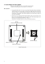
Mount the attached NQPACK on the user system before using this product.
The header board and adapter board are connected in a stack structure.
■
Connection
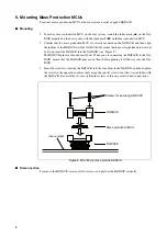
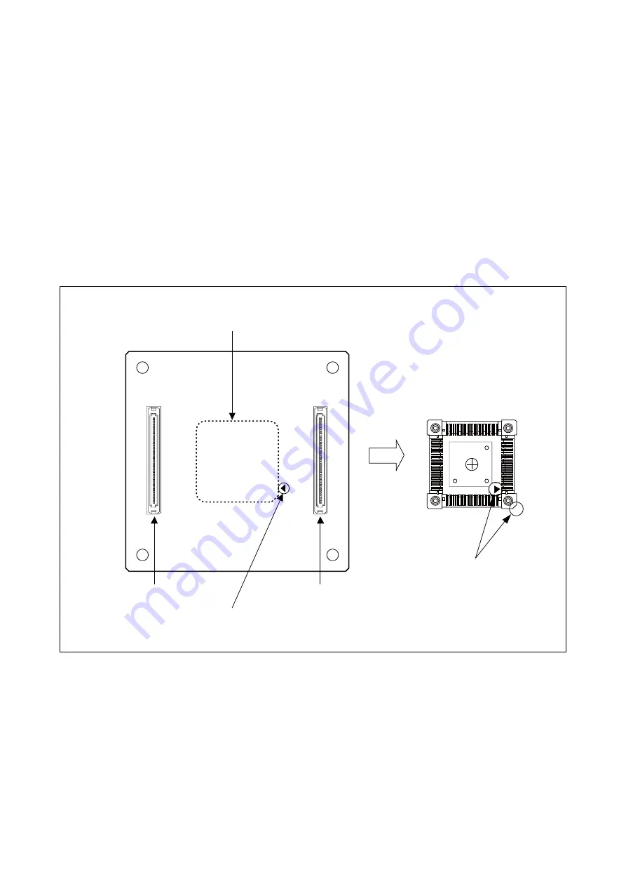
1. To connect the header board to the user system, match pin 1 indicated by the index mark (
▲
) on
the NQPACK mounted on the user system with the index mark (
▲
) on the header board and then
insert it (see “Figure 3”). The YQPACK pins are thin and easily bent. When you are connecting
the YQPACK to the NQPACK, ensure that the YQPACK pins are not bent before pushing it all
the way into the NQPACK.
2. Insert the screws for securing the header board through the washers into the four holes on the
header board, and then tighten the screws in the opposite corners evenly using the special screw
driver that was included with the NQPACK (see “Figure 4”).
Be careful not to over-tighten the screws as this may result in bad connections.
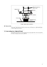
Figure 3 Index position
1
2
119
120
1
2
119
120
CN2
CN3
CN1
NQPACK index (
▲
)
Header board index (
▲
)
YQPACK
(mounted on the soldered surface)
Adapter I/F connector 2
Adapter I/F connector 1
Summary of Contents for MB2147-01
Page 10: ......
Page 11: ...FUJITSU LIMITED DSU FR EMULATOR MB2198 01 HARDWARE MANUAL ...
Page 12: ......
Page 20: ...viii ...
Page 22: ...x ...
Page 56: ...34 CHAPTER 2 CONNECTION METHOD ...
Page 64: ...42 CHAPTER 3 OPERATION METHOD ...
Page 66: ......
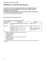
Page 76: ...54 APPENDIX B User System Specifications ...
Page 78: ......
Page 92: ......


