


FR Family MB2198-01 Emulating and Debugging Installation Guide, Doc. No. 002-05223 Rev. *A
12
4. Breakpoints and Program Stepping
How to Set Break Points and How to Use Single Steps
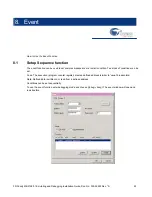
4.1
Setting Break Points
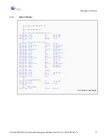
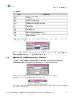
Each assembler line in the mixed mode display of the source code has a blue arrow and a green circle symbol:
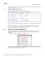
In these line a breakpoint can be set by clicking into the circle. The symbol then turns to
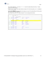
4.2
Using a Break Point
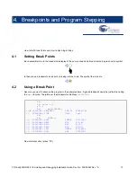
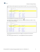
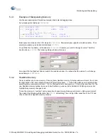
Assume you want to examine the program in the example above. A good breakpoint would be just before calling
the
wait
-function. Therefore set the breakpoint to Address
H’000C01E2
.
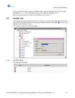
Now start execution (press “F5”).
25:
26: while (1)
27: {
28:
wait(20000);
=>
(
X
)
000C01E2: 9B044E20 LDI:20 #04E20,R4
=>
( )
000C01E6: D7DB CALL \wait
29:
30:
PDR1++;
=>
(
)
000C01E8: 0A01 DMOVB @001,R13
=>
(
)
000C01EA: 8BD0 MOV R13,R0
=>
(
)
000C01EC: A410 ADD #1,R0
=>
(
)
000C01EE: 8B0D MOV R0,R13
=>
(
)
000C01F0: 1A01 DMOVB R13,@001
=>
(
)
000C01F2: E0F7 BRA 000C01E2
31: }
32: }
000C01F4: 9F90 LEAVE
000C01F6: 0781 LD @R15+,RP
Summary of Contents for MB2147-01
Page 10: ......
Page 11: ...FUJITSU LIMITED DSU FR EMULATOR MB2198 01 HARDWARE MANUAL ...
Page 12: ......
Page 20: ...viii ...
Page 22: ...x ...
Page 56: ...34 CHAPTER 2 CONNECTION METHOD ...
Page 64: ...42 CHAPTER 3 OPERATION METHOD ...
Page 66: ......
Page 76: ...54 APPENDIX B User System Specifications ...
Page 78: ......
Page 92: ......


