
FR Family MB2198-01 Emulating and Debugging Installation Guide, Doc. No. 002-05223 Rev. *A
16
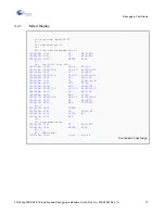
5. Monitoring and Manipulating
How to Monitor and Manipulate CPU Registers, Variables, Memory
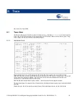
5.1
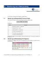
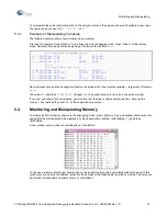
Monitoring and Manipulating Processor Status
The Condition Code Register (CCR) is always displayed below the workspace window.
The flags are:
Abbr.
Flag name
S
Stack flag (0 = User stack; 1 = System stack)
I
Interrupt enable flag (1 = enable)
N
Negative flag (MSB = 1 in last operation)
Z
Zero flag (Last operation resulted in “0”)
V
Overflow flag (Overflow at last operation)
C
Carry flag (Last operation caused carry)
The value of the flags can be easily changed by clicking into the white square. A “check mark” (
) indicates that
the flag is set (== 1).
5.2
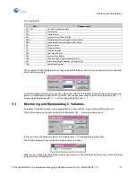
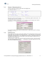
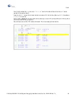
Monitoring and Manipulating CPU Registers
To display the CPU Registers window choose in the debugging mode:
View
Register
. A new window will occur
and look like this:
Summary of Contents for MB2147-01
Page 10: ......
Page 11: ...FUJITSU LIMITED DSU FR EMULATOR MB2198 01 HARDWARE MANUAL ...
Page 12: ......
Page 20: ...viii ...
Page 22: ...x ...
Page 56: ...34 CHAPTER 2 CONNECTION METHOD ...
Page 64: ...42 CHAPTER 3 OPERATION METHOD ...
Page 66: ......
Page 76: ...54 APPENDIX B User System Specifications ...
Page 78: ......
Page 92: ......


