Monitoring and Manipulating
FR Family MB2198-01 Emulating and Debugging Installation Guide, Doc. No. 002-05223 Rev. *A
18
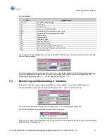
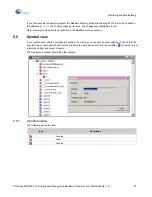
To manipulate the value just double-click on the entry and enter in the pop-up window
Edit variable
a new value.
The radix can be chosen via “
D’
”, “
H’
”, “
B’
”, or “
O’
”.
5.3.1
Example of Manipulating Variables
The following example shows how to intervene in a program.
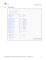
First use the example C code “Main.c” from above and enter debugging mode. Open “Main.c” in
Mix display
mode. Now set a break point at the beginning of the loop in the function
wait
.
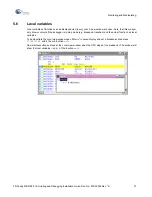
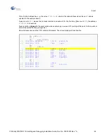
Now start execution and the debugger will halt on the break point. Next, display variable
a
, (argument of function
wait
).
The value of
a
should be
H’4E200000
. Change
a
to 1 by double clicking to its entry in the watch window.
If you now use step-in for several times, you will note, that the loop is only executed one time, because the
counter
i
has reached the count of
1
of the comparison argument
a
.
5.4
Monitoring and Manipulating Memory
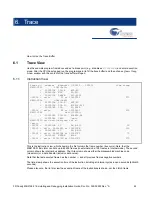
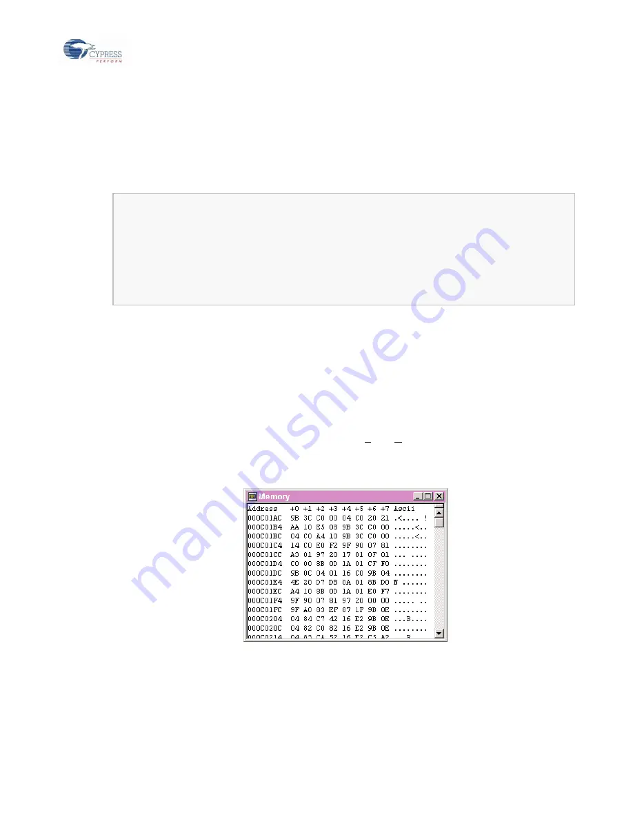
To display the MCU memory choose in the debugging mode:
View
Memory
. A pop-up window
Watch
will occur
and ask for the start address to be displayed. Type a hexadecimal number (with leading
H’
) and press
<RETURN>.
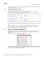
A new window occurs which is something like a
“Hex-Editor”:
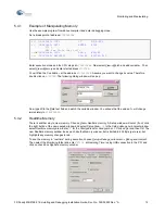
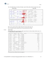
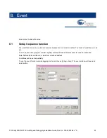
To change a memory content just double click on the respecting byte and a new dialog window pops up. In this
window you can specify the address (default is the address of the clicked byte) and the new value. The value can
be entered in hexadecimal, decimal, binary or octal format.
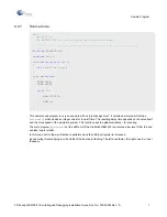
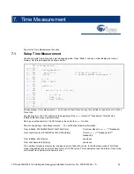
16: void wait(unsigned int a)
=>
(
)
000C019E: 1704 ST R4,@-R15
=>
(
)
000C01A0: 1781 ST RP,@-R15
=>
(
)
000C01A2: 0F01 ENTER #004
17: {
18: for (i=0; i<a; i++);
=>
(
X
)
000C01A4: C000 LDI:8 #00,R0
=>
(
)
000C01A6: 9B3CC000 LDI:20 #3C000,R12
=>
(
)
000C01AA: 14C0 ST R0,@R12
=>
(
)
000C01AC: 9B3CC000 LDI:20 #3C000,R12
000C01B0: 04C0 LD @R12,R0
Summary of Contents for MB2147-01
Page 10: ......
Page 11: ...FUJITSU LIMITED DSU FR EMULATOR MB2198 01 HARDWARE MANUAL ...
Page 12: ......
Page 20: ...viii ...
Page 22: ...x ...
Page 56: ...34 CHAPTER 2 CONNECTION METHOD ...
Page 64: ...42 CHAPTER 3 OPERATION METHOD ...
Page 66: ......
Page 76: ...54 APPENDIX B User System Specifications ...
Page 78: ......
Page 92: ......

