7
4. Operating Procedures
This section describes the power-on and off sequences. Be sure to read this section before turning the
power on.
■
Power-on Sequence
To turn the power on, follow the procedure shown in Figure 6 after making all devices connected.
The emulator power can be turned on by pressing down the power switch on the rear of the emulator.
The switch then remains in the depressed position.
See the hardware manual of the emulator for details on the position of the power switch.
The power to the adapter is turned on using the power switch on the adapter. See the “F
2
MC-16FX BGA-
416P ADAPTER MB2198-500 OPERATION MANUAL” for the position of the power switch on the
adapter.
The emulator needs to be initialized (monitor loading) immediately before the power is turned on to the
user system in a factory default state. See the “S
OFTUNE
Workbench OPERATING MANUAL” for details
on the initialization procedure.
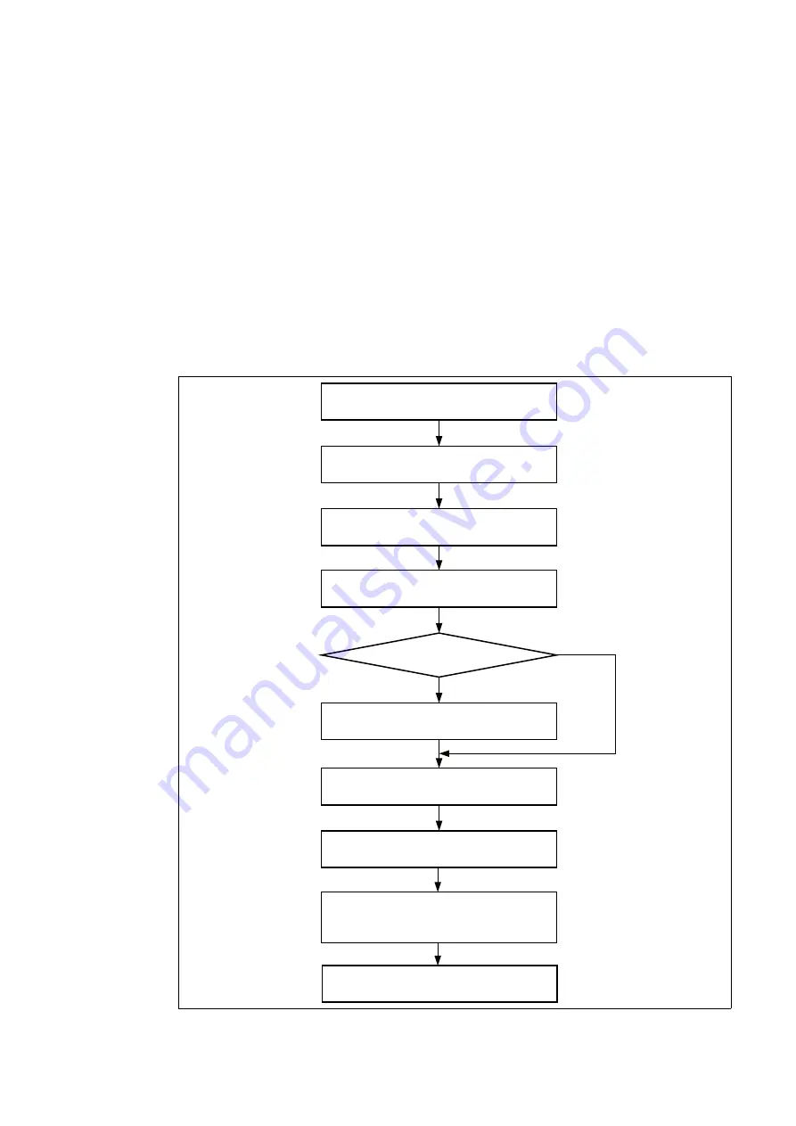
Figure 6 Power-on sequence
Turn on the host computer
Turn on the emulator
Run S
OFTUNE
Workbench
Run Emulator Debugger
Has the emulator
been initialized?
Perform the emulator initialization
Check that the dialog box is displayed
(See Figure 7)
Turn on the adapter
Click [OK] in the dialog box
The POWER LED on the emulator lights up
NO
YES
Connect the AC adapter to the DC jack
on the adapter to supply power
to the trace board
The adapter power LED on the trace board lights up
The trace board power LED lights up


