8
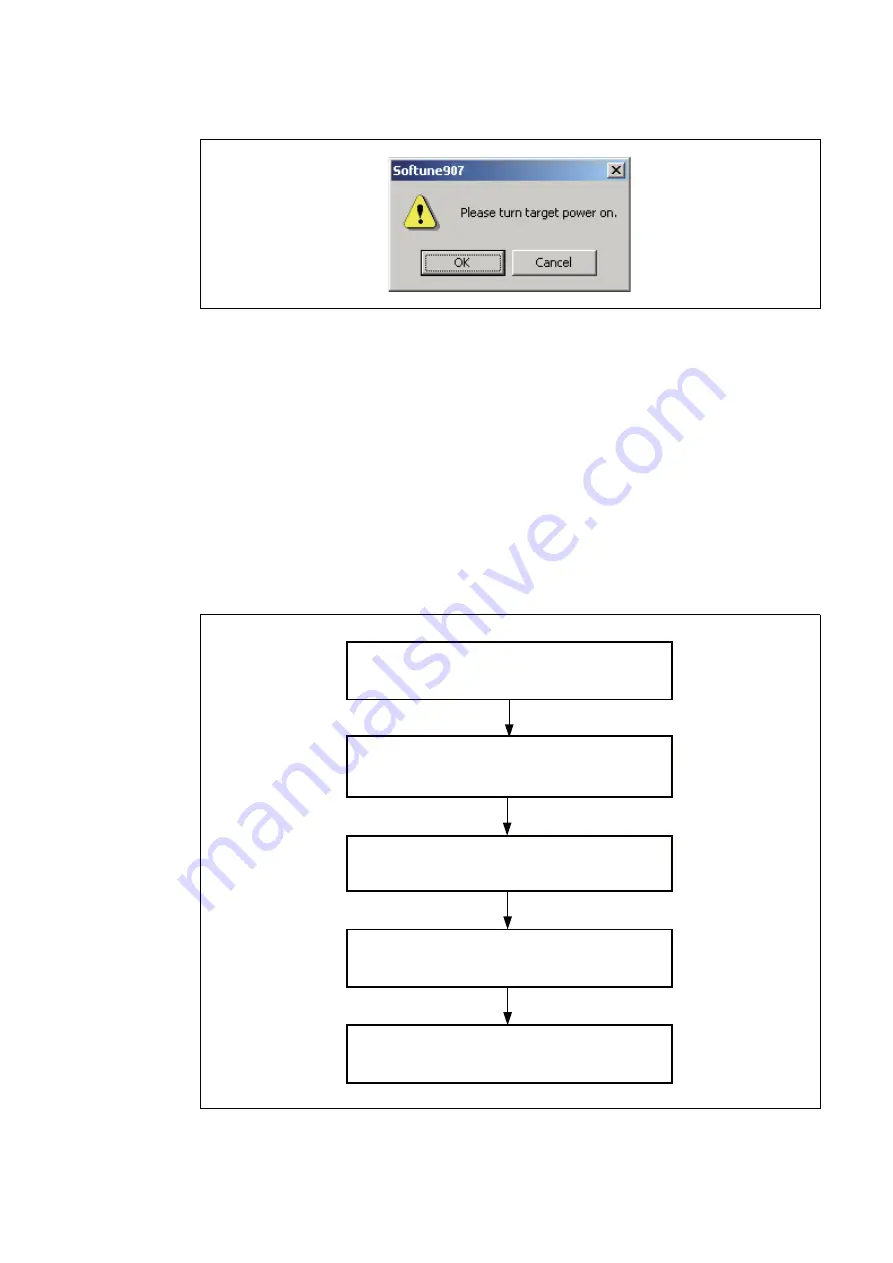
Figure 7 Dialog box displayed
Note : When the power is turned on to the user system, the adapter power LED on the trace board and the USER
POWER LED on the adapter light up. Additionally, when the AC adapter is connected to the DC jack on
the adapter, the Trace Board Power LED on the trace board lights up. If a LED does not light up when the
power is turned on, quickly disconnect the power to the entire system, and turn the power on again after
resolving the problem by checking such that there are no incorrect connections.
■
Power-off Sequence
Turn the power off by following the procedure shown in Figure 8.
The emulator power can be turned off by pressing down and releasing the power switch on the rear of the
emulator. The depressed switch then returns to the off position (the unpressed position).
See the hardware manual of the emulator for details on the position of the power switch.
Turn off the power to the adapter using the power switch on the adapter. See the "F
2
MC-16FX BGA-
416P Adapter MB2198-500 Operation Manual" for the position of the power switch on the adapter.
Figure
8
Power-off sequence
Exit Emulator Debugger
Turn off the adapter power
Turn off the power to the emulator
Turn off the host computer
(as required)
Remove the AC adapter from the DC jack on the
adapter to turn off the power to the trace board.


