background image

10

Table 5 Adapter Connector Pin Assignment

Connector

pin number

Pin name

Connector

pin number

Pin name

Connector

pin number

Pin name

Connector

pin number

Pin name

1

DC16V

41

TRDYX

81

TDT[30]

121

TDT[62]

2

DC16V

42

TOEX

82

TDT[31]

122

TDT[63]

3

DC16V

43

GND

83

GND

123

GND

4

DC16V

44

GND

84

GND

124

GND

5

DC16V

45

TDT[0]

85

TDT[32]

125

TAD[0]

6

DC16V

46

TDT[1]

86

TDT[33]

126

TAD[1]

7

MNT[0]

47

TDT[2]

87

TDT[34]

127

TAD[2]

8

MNT[1]

48

TDT[3]

88

TDT[35]

128

TAD[3]

9

MNT[2]

49

TDT[4]

89

TDT[36]

129

TAD[4]

10

MNT[3]

50

TDT[5]

90

TDT[37]

130

TAD[5]

11

MNT[4]

51

TDT[6]

91

TDT[38]

131

TAD[6]

12

MNT[5]

52

TDT[7]

92

TDT[39]

132

TAD[7]

13

GND

53

GND

93

GND

133

GND

14

GND

54

GND

94

GND

134

GND

15

MNT[6]

55

TDT[8]

95

TDT[40]

135

TAD[8]

16

MNT[7]

56

TDT[9]

96

TDT[41]

136

TAD[9]

17

MNT[8]

57

TDT[10]

97

TDT[42]

137

TAD[10]

18

MNT[9]

58

TDT[11]

98

TDT[43]

138

TAD[11]

19

MNT[10]

59

TDT[12]

99

TDT[44]

139

TAD[12]

20

MNT[11]

60

TDT[13]

100

TDT[45]

140

TAD[13]

21

MNT[12]

61

TDT[14]

101

TDT[46]

141

TAD[14]

22

MNT[13]

62

TDT[15]

102

TDT[47]

142

TAD[15]

23

GND

63

GND

103

GND

143

GND

24

GND

64

GND

104

GND

144

GND

25

MNT[14]

65

TDT[16]

105

TDT[48]

145

TAD[16]

26

MNT[15]

66

TDT[17]

106

TDT[49]

146

TAD[17]

27

MNT[16]

67

TDT[18]

107

TDT[50]

147

TAD[18]

28

MNT[17]

68

TDT[19]

108

TDT[51]

148

TAD[19]

29

MNT[18]

69

TDT[20]

109

TDT[52]

149

TAD[20]

30

MNT[19]

70

TDT[21]

110

TDT[53]

150

TAD[21]

31

MNT[20]

71

TDT[22]

111

TDT[54]

151

TAD[22]

32

EXTTRC

72

TDT[23]

112

TDT[55]

152

TAD[23]

33

GND

73

GND

113

GND

153

GND

34

GND

74

GND

114

GND

154

GND

35

TCLK

75

TDT[24]

115

TDT[56]

155

TAD[24]

36

EXTTRCX

76

TDT[25]

116

TDT[57]

156

TAD[25]

37

GND

77

TDT[26]

117

TDT[58]

157

TAD[26]

38

TADCSX

78

TDT[27]

118

TDT[59]

158

TAD[27]

39

TWRX

79

TDT[28]

119

TDT[60]

159

VCC

40

TEMUL

80

TDT[29]

120

TDT[61]

160

VCC

Summary of Contents for MB2198-590-E

Page 1: ...The following document contains information on Cypress products ...

Page 2: ...FUJITSU SEMICONDUCTOR SUPPORT SYSTEM SS01 71076 1E DSU FR EMULATOR F2 MC 16FX EXPANSION TRACE BOARD MB2198 590 E OPERATION MANUAL ...

Page 3: ... without notice Note that Fujitsu shall accept no responsibility for any consequences arising either directly or indirectly from the use of this product Product Operating Environment Use the product at an operating temperature of between 5 C and 35 C and at an operating humidity of between 20 to 80 Use the product in an environment that is free of condensation and avoid high tem perature or humidi...

Page 4: ...European RoHS compliant products Notice on this document All information included in this document is current as of the date it is issued Such information is subject to change without any prior notice Please confirm the latest relevant information with the sales representatives ...

Page 5: ...ese sharp edges Damage Do not place anything on the product or expose the product to physical shocks Do not carry the product after the power has been turned on Doing so may cause a malfunc tion due to overloading or shock Damage Since the product contains many electronic components keep it away from direct sun light high temperature and high humidity to prevent condensation Do not use or store th...

Page 6: ...in this document are designed developed and manufactured as contemplated for general use in cluding without limitation ordinary industrial use general office use personal use and household use but are not de signed developed and manufactured as contemplated 1 for use accompanying fatal risks or dangers that unless extremely high safety is secured could have a serious effect to the public and could...

Page 7: ...use a Fujitsu F2 MC 16FX family microcontroller Verifying the Contents of the Package Check that all of the following components are present in the package before using the trace board Trace board 1 AC adapter 1 Locking screws 1 set 2 screws Operation manual English this manual 1 Operation manual Japanese 1 Related Products The optional products shown in Table 1 are available for the adapter Purch...

Page 8: ... the emulator See 3 Connection for details on how to connect the adapter and the header board See the hardware manual and operation manual of the emulator and adapter for the specifications of these components Host computer External trigger Program execution General purpose measurement device AC adapter Flat cable Adapter Evaluation MCU MB96V300 Adapter board Header board User system Header DSU FR...

Page 9: ...396 R397 R398 R399 C58 C57 C77 R335 M17 R336 R337 R338 R339 R340 R341 R342 C55 C54 C56 C53 R285 M16 R286 R279 R280 R281 R282 R283 R284 R480 C118 C116 M37 RN16 GND C137 C139 C117 R481 R482 R483 R484 R485 R486 R487 R536 M44 R537 R538 R539 R540 R541 R542 R543 C93 C92 C138 R416 M29 R417 R418 R419 R421 R423 R426 R427 C115 C113 C94 R472 M36 R473 R474 R475 R476 R477 R478 R479 C69 C68 C114 R352 M25 R353 R...

Page 10: ...51 R450 R449 R447 R446 R445 R444 R448 M30 C88 C95 C96 R455 R454 R453 R425 R424 R422 R420 R452 M27 C73 C86 C87 R383 R382 R381 R379 R378 R377 R376 R380 M22 C64 C71 C72 R391 R390 R389 R387 R386 R385 R384 R388 M19 C49 C62 C63 R350 R349 R348 R346 R345 R344 R343 R347 M14 C47 C48 R278 R277 R276 R274 R273 R272 R271 R275 RB4 C43 C41 C39 C37 C25 C26 R170 R142 R147 R144 R149 R136 R141 R140 R92 R90 R91 R89 C2...

Page 11: ...pter fix the two boards together using the locking screws 3 Connection Connecting the Adapter See Figure 4 to connect the trace board See the operation manual of the F2 MC 16FX BGA 416P adapter model number MB2198 500 and the F2 MC 16FX QFP 100P header type3 model number MB2198 501 for details on connecting the adapt er and header to the user system Figure 4 Connecting the trace board Emulator Ada...

Page 12: ... the adapter 3 Insert the AC plug into a power outlet Note The power supply to the trace board is supplied by connecting the AC adapter to the adapter As there is no power switch on the trace board connect the AC adapter in the correct sequence within the power on sequence See 4 Operating Procedures Power on Sequence and Power off Sequence for details on the power on sequence Figure 5 Connecting t...

Page 13: ...0 OPERATION MANUAL for the position of the power switch on the adapter The emulator needs to be initialized monitor loading immediately before the power is turned on to the user system in a factory default state See the SOFTUNE Workbench OPERATING MANUAL for details on the initialization procedure Figure 6 Power on sequence Turn on the host computer Turn on the emulator Run SOFTUNE Workbench Run E...

Page 14: ...f by following the procedure shown in Figure 8 The emulator power can be turned off by pressing down and releasing the power switch on the rear of the emulator The depressed switch then returns to the off position the unpressed position See the hardware manual of the emulator for details on the position of the power switch Turn off the power to the adapter using the power switch on the adapter See...

Page 15: ...nsion trace board Product model MB2198 590 E Memory capacity 2 GB 512Mbit SDRAM 32 Input power Maximum 16V 2 5A Supplied by adapter DC jack Operating voltage 3 3V FPGA I O SDRAM Generates 5V from 16V Generates 3 3V and 1 2V from 5V 1 2V FPGA internal Operating frequency Max 66MHz Operating temperature Storage temperature 5 C to 35 C 0 C to 70 C No condensation Operating humidity Storage humidity 2...

Page 16: ...NT 8 57 TDT 10 97 TDT 42 137 TAD 10 18 MNT 9 58 TDT 11 98 TDT 43 138 TAD 11 19 MNT 10 59 TDT 12 99 TDT 44 139 TAD 12 20 MNT 11 60 TDT 13 100 TDT 45 140 TAD 13 21 MNT 12 61 TDT 14 101 TDT 46 141 TAD 14 22 MNT 13 62 TDT 15 102 TDT 47 142 TAD 15 23 GND 63 GND 103 GND 143 GND 24 GND 64 GND 104 GND 144 GND 25 MNT 14 65 TDT 16 105 TDT 48 145 TAD 16 26 MNT 15 66 TDT 17 106 TDT 49 146 TAD 17 27 MNT 16 67 ...

Page 17: ... seen from the DSU side Figure 9 DSU side trace memory write timing Address Data WRITE TCLK TEMUL TRDYX TAD 27 0 TWRX TOEX TDT 63 0 TADSCX 1 2 3 4 3 4 3 4 5 6 Symbol Description Min Max Units 1 TEMUL setup time 3 ns 2 TEMUL hold time 3 ns 3 TADSCX setup time 3 ns 4 TADSCX hold time 3 ns 5 Data setup time 3 ns 6 Data hold time 3 ns ...

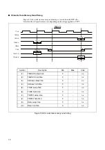
Page 18: ...0 DSU side trace memory read timing TEMUL TRDYX TAD 27 0 TWRX TOEX TDT 63 0 TADSCX TCLK 1 2 5 3 4 6 7 8 9 10 Address Data READ Symbol Description Min Max Units 1 TADSCX setup time 3 ns 2 TADSCX hold time 3 ns 3 Address setup time 3 ns 4 Address hold time 3 ns 5 TOEX setup time 3 ns 6 TOEX hold time 3 ns 7 TRDYX setup time 3 ns 8 TRDYX hold time 3 ns 9 Data setup time 3 ns 10 Data hold time 3 ns ...

Page 19: ...MICONDUCTOR SUPPORT SYSTEM DSU FR EMULATOR F2 MC 16FX EXPANSION TRACE BOARD MB2198 590 E OPERATION MANUAL February 2008 the first edition Published FUJITSU LIMITED Electronic Devices Edited Strategic Business Development Dept ...

Page 20: ......

Reviews: