MB3773
15
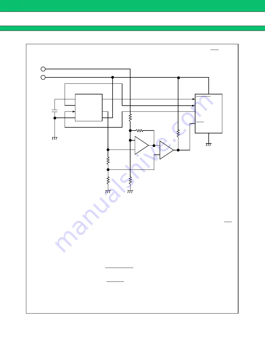
EXAMPLE 4: Monitoring Two Supply Voltages (with hysteresis, reset output and NMI)
V
CC1
(5 V)
1
2
3
4
8
7
6
5
MB3773
RESET
RESET
CK
GND
Comp. 2
Example : Comp. 1, Comp. 2
: MB4204, MB47393
NMI or port
R
6
+
_
+
_
V
CC2
(12 V)
180 k
Ω
R
4
30 k
Ω
R
3
5.1 k
Ω
R
2
1.2 k
Ω
R
1
4.7 k
Ω
R
5
Comp. 1
Notes :
•
The 5 V supply voltage is monitored by the MB3773.
•
The 12 V supply voltage is monitored by the external circuit. Its output is connected to the NMI
terminal and, when voltage drops, Comp. 2 interrupts the logic circuit.
•
Use V
CC1
(
=
5 V) to power the comparators (Comp. 1 and Comp. 2) in the external circuit shown
above.
•
The detection voltage of the V
CC2
(
=
12 V) supply voltage is approximately 9.2 V/9.4 V and has
a hysteresis width of approximately 0.2 V.
V
CC2
detection voltage and hysteresis width can be found using the following formulas:
→
Detection voltage
→
Hysteresis width
V
HYS
=
V
2H
−
V
2L
R
3
+
(R
4
// R
5
)
R
4
// R
5
×
V
REF
V
2L
=
R
3
+
R
5
R
5
×
V
REF
(Approximately 9.4 V in the above illustration)
(Approximately 9.2 V in the above illustration)
C
T
Logic circuit
V
2H
=
10 k
Ω


