background image

MB39A104

31

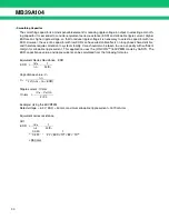
CH2

Capacitance value

CH1

CH2

Ripple current

CH1

CH2

ESR  


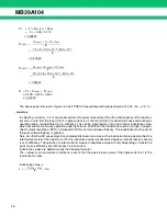
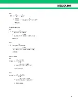
V

O


1

I

L

2

π

fC

L


0.033


1

0.364

2

π


×

 500 

×

 10

3


×

 82 

×

 10

6


 86.8 m

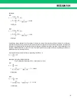
C

L


I

L

2

π

f (

V

O


I

L


×

 ESR) 


0.491

2

π


×

 500 

×

 10

3


×

  (0.050 

 0.491 

×

 0.05) 


 6.14 

µ

F

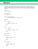
C

L


I

L

2

π

f (

V

O


I

L


×

 ESR) 


0.364

2

π


×

 500 

×

 10

3


×

  (0.033 

 0.364 

×

 0.05) 


 7.83 

µ

F

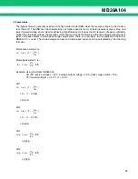
IC

L

rms  


 (V

IN


 V

O

) ton

2

3L


 (19 

 5)  

×

 0.263

2

×

 15 

×

 10

6


×

 500 

×

 10

3


  141.7 mArms

IC

L

rms  


 (V

IN


 V

O

) ton

2

3L


 (19 

 3.3)  

×

 0.174

2

×

 15 

×

 10

6


×

 500 

×

 10

3


  105.1 mArms

Summary of Contents for MB39A104

Page 1: ...sion Operating at high frequency reduces the value of coil This is ideal for built in power supply such as LCD monitors and ADSL This product is covered by US Patent Number 6 147 477 FEATURES Built in timer latch overcurrent protection circuit requiring no current sense resistor Power supply voltage range 7 V to 19 V Reference voltage 5 0 V 1 Error amplifier threshold voltage 1 24 V 1 High frequen...

Page 2: ... 2 PIN ASSIGNMENTS TOP VIEW FPT 24P M03 1 2 3 4 5 6 7 8 9 10 11 12 VCCO VH OUT1 VS1 ILIM1 DTC1 VCC CSCP FB1 INE1 CS1 RT 24 23 22 21 20 19 18 17 16 15 14 13 CTL GNDO OUT2 VS2 ILIM2 DTC2 GND VREF FB2 INE2 CS2 CT ...

Page 3: ...ut terminal 11 CS1 Soft start capacitor connection terminal 12 RT Triangular wave oscillation frequency setting resistor connection terminal 13 CT Triangular wave oscillation frequency setting capacitor connection terminal 14 CS2 Soft start capacitor connection terminal 15 INE2 I Error amplifier Error Amp 2 inverted input terminal 16 FB2 O Error amplifier Error Amp 2 output terminal 17 VREF O Refe...

Page 4: ...ogic UVLO OSC VREF Bias Voltage Current Protection Logic Current Protection Logic IO 200 mA at VCCO 12 V IO 200 mA at VCCO 12 V VR1 VH 1 24 V 2 5 V 1 5 V 5 0 V bias Power ON OFF CTL P ch Drive2 P ch Drive1 PWM Comp 1 PWM Comp 2 Error Amp2 Error Amp1 CH1 CH2 INE1 INE2 10 µA VCC 5 V 10 µA L priority L priority L priority L priority H priority H at SCP H UVLO release Accuracy 1 H at OCP Error Amp Pow...

Page 5: ...eir representatives beforehand Parameter Symbol Condition Rating Unit Min Max Power supply voltage VCC VCC VCCO terminal 20 V Output current IO OUT1 OUT2 terminal 60 mA Output peak current IOP Duty 5 t 1 fOSC Duty 700 mA Power dissipation PD Ta 25 C 740 mW Storage temperature TSTG 55 125 C Parameter Symbol Condition Value Unit Min Typ Max Power supply voltage VCC VCC VCCO terminal 7 12 19 V Refere...

Page 6: ...0 V VTHL 17 VREF 2 4 2 6 2 8 V Hysteresis width VH 17 0 2 V 3 Short circuit detection block SCP Logic Threshold voltage VTH 8 0 68 0 73 0 78 V Input source current ICSCP 8 1 4 1 0 0 6 µA Reset voltage VRST 17 VREF 2 4 2 6 2 8 V 4 Short circuit detection block SCP Comp Threshold voltage VTH 8 2 8 3 1 3 4 V 5 Triangular wave oscillator block OSC Oscillation frequency fOSC 13 CT 100 pF RT 24 kΩ 450 5...

Page 7: ...rotection circuit block OCP1 OCP2 ILIM terminal input current ILIM 5 20 RT 24 kΩ CT 100 pF 99 110 121 µA Offset voltage VIO 5 20 1 mV 10 Bias voltage block VH Output voltage VH 2 VCC VCCO 7 V to 19 V VH 0 mA to 30 mA VCC 5 5 VCC 5 0 VCC 4 5 V 11 Output block Drive1 Drive2 Output source current ISOURCE 3 22 OUT1 to OUT4 7 V Duty 5 t 1 fOSC Duty 300 mA Output sink current ISINK 3 22 OUT1 to OUT4 12 ...

Page 8: ... 9 8 7 6 5 4 3 2 1 0 0 5 10 15 20 ICTL VREF Power supply current I CC mA Reference voltage V REF V Power Supply Current vs Power Supply Voltage Reference Voltage vs Power Supply Voltage Power supply voltage VCC V Power supply voltage VCC V Reference Voltage vs Ambient Temperature Reference voltage V REF V Load current IREF mA Reference voltage V REF Reference Voltage vs Load current Ambient temper...

Page 9: ...T V Ambient temperature Ta C Triangular Wave Oscillation Frequency vs Timing Resistor Triangular wave oscillation frequency f OSC kHz Timing resistor RT kΩ Triangular Wave Oscillation Frequency vs Timing Capacitor Triangular wave oscillation frequency f OSC kHz Timing capacitor CT pF Triangular Wave Oscillation Frequency vs Ambient Temperature Triangular wave oscillation frequency f OSC kHz Ambien...

Page 10: ... 30 20 10 0 10 20 30 40 180 90 0 90 180 100 1 k 10 k 100 k 1 M 10 M Ta 25 C VCC 12 V AV ϕ 1000 800 600 400 200 0 740 40 20 0 20 40 60 80 100 Error Amplifier Gain Phase vs Frequency Gain A V dB Phase φ deg Frequency f Hz Power Dissipation vs Ambient Temperature Power dissipation P D mW Ambient temperature Ta C ...

Page 11: ...g a feedback resistor and capacitor from the output terminal to inverted input terminal of the error amplifier enabling stable phase compensation to the system Also it is possible to prevent rush current at power supply start up by connecting a soft start capacitor with the CS1 terminal pin 11 and CS2 terminal pin 14 which are the non inverted input terminal for Error Amp The use of Error Amp for ...

Page 12: ...r SCP Comp detects the output voltage level of Error Amp and if the error amp output voltage of any channel falls below the short circuit detection voltage 3 1 V Typ the timer circuits are actuated to start charging the external capacitor CSCP connected to the CSCP terminal pin 8 When the capacitor voltage reaches about 0 73 V the circuit is turned off the output transistor and sets the dead time ...

Page 13: ...atly than the calculated values according to the constant of timing resistor RT when the triangular wave oscillation frequency exceeds 1 MHz Therefore set it referring to Triangular Wave Oscillation Frequency vs Timing Resistor and Triangular Wave Oscillation Frequency vs Timing Capacitor in TYPICAL CHARACTERISTICS Triangular oscillation frequency fOSC 15 10 14 CS2 CS1 INE2 INE1 VO R1 R2 1 24 V Er...

Page 14: ...ison between the lower one of the potentials at two non inverted input terminals 1 24 V CS1 terminal voltages and the inverted input terminal voltage INE1 pin 10 voltage INE2 pin 15 voltage The FB1 FB2 terminal voltage is decided for the soft start period by the comparison between 1 24 V in an internal reference voltage and the voltages of the CS1 CS2 terminal The DC DC converter output voltage ri...

Page 15: ...MB39A104 15 16 9 10 15 R1 R2 INE2 CS1 CS2 CS1 CS2 INE1 10 µA FB1 FB2 VREF VO Error Amp UVLO 1 24 V 11 14 L priority CH ON OFF signal L ON H OFF Soft Start Circuit ...

Page 16: ...MB39A104 16 TREATMENT WITHOUT USING CS TERMINAL When not using the soft start function open the CS1 terminal pin 11 and the CS2 terminal pin 14 11 CS1 14 CS2 OPEN OPEN Without Setting Soft Start Time ...

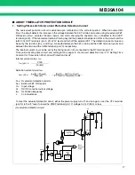
Page 17: ...the drain and the ILIM2 terminal pin 20 respectively The internal current ILIM can be set by the timing resistor RT connected to the RT terminal pin 12 Time until activating timer circuit and setting latch is equal to short circuit detection time in 2 Setting Time Constant for Timer Latch Short Circuit Protection Circuit Internal current value ILIM Detection current value IOCP RLIM Overcurrent det...

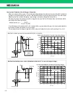
Page 18: ...f an overcurrent detection resistor RS to detect overcurrent as shown below This example shows the range of operation of the overcurrent detection function with a setting of Vo 3 3V ON interval 450 ns VO V VIN V fOSC Hz 20 4 21 ILIM1 ILIM2 VS1 VS2 VIN Error Amp Q1 5 Rs 1600 1400 1200 1000 800 400 200 0 6 8 10 12 14 VCC V f OSC kHz 16 18 20 Overcurrent Detection Function Operating Range VO set to 3...

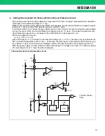
Page 19: ...auses the external short circuit protection capacitor CSCP connected to the CSCP terminal to be charged at 1 µA Short circuit detection time tSCP tSCP s 0 73 CSCP µF When the capacitor CSCP is charged to the threshold voltage VTH 0 73 V the latch is set and the external FET is turned off dead time is set to 100 At this time the latch input is closed and the CSCP terminal pin 8 is held at L level I...

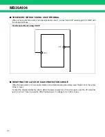
Page 20: ...H OF EACH PROTECTION CIRCUIT When the overcurrent or short circuit protection circuit detects each abnormality it sets the latch to fix the output at the L level To reset the actuated protection circuit either the power supply turn off and on again or set the CTL terminal pin 24 to the L level to lower the VREF terminal pin 17 voltage to 2 4 V Min or less 8 CSCP 18 GND Treatment without using CSCP...

Page 21: ...GND 3 1 V 13 INEX CSX GND VCC VREF 5 0 V FBX 1 24 V ILIMX GND GNDO VCCO VSX VCC DTCX GND VCC FBX CT VCC GND VCCO VH GNDO 2 X Each channel No Reference voltage block Control block Soft start block Short circuit detection block Triangular wave oscillator block RT Triangular wave oscillator CT block Error amplifier block CH1 CH2 Overcurrent protection circuit block PWM comparator block CH1 CH2 Output...

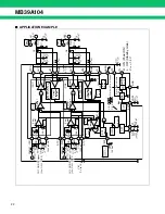
Page 22: ...24 V 3 1 V SCP Comp SCP Logic UVLO OSC VREF Bias Voltage Current Protection Logic Current Protection Logic I O 200 mA at VCCO 12 V I O 200 mA at VCCO 12 V VR1 VH 1 24 V 2 5 V 1 5 V 5 0 V bias Power ON OFF CTL P ch Drive2 P ch Drive1 PWM Comp 1 PWM Comp 2 Error Amp2 Error Amp1 CH1 CH2 Step down Step down L priority L priority L priority L priority H priority accuracy 1 H UVLO release H at OCP H at ...

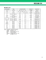
Page 23: ...er OS CONTM Ceramics Condenser OS CONTM Ceramics Condenser Ceramics Condenser Ceramics Condenser 100 pF 10 µF 10 µF 82 µF 0 1 µF 1000 pF 0 1 µF 50 V 20 V 25 V 6 3 V 50 V 50 V 50 V TDK SANYO TDK SANYO TDK TDK TDK C1608CH1H101J 20SVP10M C3225JF1E106Z 6SVP82M C1608JB1H104K C1608JB1H102K C1608JB1H104K R1 R4 R5 R8 R13 R9 R14 R10 R11 R15 R16 Resistor Resistor Resistor Resistor Resistor Resistor Resistor...

Page 24: ... The selection must ensure that peak drain current does not exceed rated values and also must be in accordance with overcurrent detection levels Continuity loss PC On cycle switching loss PS ON Off cycle switching loss PS OFF Total loss PT PT PC PS ON PS OFF Example Using the Toshiba TPC8102 CH1 Input voltage VIN Max 19 V output voltage VO 5 V drain current ID 3 A Oscillation frequency fOSC 500 kH...

Page 25: ...source on resistance RDS ON 50 mΩ tr tf 100 ns Drain current Max ID Max Drain current Min ID Min PC ID 2 RDS ON Duty 3 2 0 05 0 263 0 118 W PS ON VD Max ID tr fOSC 6 19 3 100 10 9 500 103 6 0 475 W PS OFF VD Max ID Max tf fOSC 6 19 3 25 100 10 9 500 103 6 0 515 W PT PC PS ON PS OFF 0 118 0 475 0 515 1 108 W ID Max IO VIN VO ton 2L 3 19 3 3 1 0 174 2 15 10 6 500 103 3 18 A ID Min IO VIN VO ton 2L 3...

Page 26: ...set at the point where efficiency is greatest Note also that the DC superimposition characteristics become worse as the load current value approaches the rated current value of the inductor so that the inductance value is reduced and ripple current increases causing loss of efficiency The selection of rated current value and inductance value will vary depending on where the point of peak efficienc...

Page 27: ...In this application the Sumida CDRH104R 150 is used At 15 µH the load current value under continuous operating conditions is determined by the following formula Load current value under continuous operating conditions IO Example Using the CDRH104R 150 15 µH allowable tolerance 30 rated current 3 6 A CH1 CH2 L 2 VIN VO ton IO 2 19 5 1 0 263 IO 500 103 4 91 µH L 2 VIN VO ton IO 2 19 3 3 1 0 174 IO 5...

Page 28: ... the ripple current can be determined by the following formulas Peak value IL Peak to peak value IL Example Using the CDRH104R 150 15 µH allowable tolerance 30 rated current 3 6 A Peak value CH1 CH2 Peak to peak value CH1 CH2 IL IO VIN VO ton 2L IL VIN VO ton L IL IO VIN VO ton 2L 3 19 5 1 0 263 2 15 10 6 500 103 3 25 A IL IO VIN VO ton 2L 3 19 3 3 1 0 174 2 15 10 6 500 103 3 18 A IL VIN VO ton L ...

Page 29: ... diode is within the average output current level and peak current is within peak surge current limits there is no problem In this application the Rohm RB053L 30 is used The diode average current and diode peak current can be calculated by the following formulas Diode mean current IDi Diode peak current IDip Example Using the Rohm RB053L 30 VR DC reverse voltage 30 V average output voltage 3 0 A p...

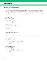
Page 30: ...op phase characteristics and therefore requires attention to system stability Care should also be taken to use a capacity with sufficient margin for allowable ripple current This application uses the OS CON TM 6SVP82M made by SANYO The ESR capacitance value and ripple current can be calculated from the following formulas Equivalent Series Resistance ESR Capacitance value CL Ripple current ICLrms E...

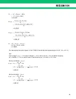
Page 31: ... 0 364 2π 500 103 82 10 6 86 8 mΩ CL IL 2πf VO IL ESR 0 491 2π 500 103 0 050 0 491 0 05 6 14 µF CL IL 2πf VO IL ESR 0 364 2π 500 103 0 033 0 364 0 05 7 83 µF ICLrms VIN VO ton 2 3L 19 5 0 263 2 3 15 10 6 500 103 141 7 mArms ICLrms VIN VO ton 2 3L 19 3 3 0 174 2 3 15 10 6 500 103 105 1 mArms ...

Page 32: ... VIN 7 V VIN 10 V VIN 19 V VIN 12 V 100 90 80 70 60 50 40 30 10 m 100 m 1 10 Conversion efficiency η Load current IL A Conversion Efficiency vs Load Current CH1 Conversion efficiency η Load current IL A Conversion Efficiency vs Load Current CH2 Ta 25 C 5 V Output SW1 OFF SW2 ON Ta 25 C 3 3 V Output SW1 ON SW2 OFF ...

Page 33: ... 0 15 10 5 0 VS V t µs Ta 25 C VIN 12 V CTL 5 V VO 5 V RL 1 67 Ω 0 1 2 3 4 5 6 7 8 9 10 VG V 15 10 5 0 15 10 5 0 VS V t µs Ta 25 C VIN 12 V CTL 5 V VO 3 3 V RL 1 1 Ω 0 1 2 3 4 5 6 7 8 9 10 Switching Wave Form CH1 Switching Wave Form CH2 ...

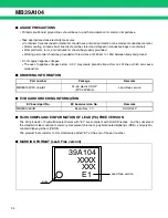
Page 34: ...f negative voltages below 0 3 V may create parasitic transistors on LSI lines which can cause malfunction ORDERING INFORMATION EV BOARD ORDERING INFORMATION RoHS COMPLIANCE INFORMATION OF LEAD Pb FREE VERSION The LSI products of Fujitsu Microelectronics with E1 are compliant with RoHS Directive and has observed the standard of lead cadmium mercury Hexavalent chromium polybrominated biphenyls PBB a...

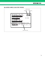
Page 35: ...ON 2006 03 01 ASSEMBLED IN JAPAN G QC PASS 3N 1MB123456P 789 GE1 1000 3N 2 1561190005 107210 1 000 PCS 0605 Z01A 1000 1 1 1561190005 MB123456P 789 GE1 MB123456P 789 GE1 MB123456P 789 GE1 Pb Lead Free version lead free mark JEITA logo JEDEC logo ...

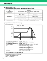
Page 36: ... the storage period after opening was exceeded Please processes within 8 days after baking 125 C 24H Storage conditions 5 C to 30 C 70 RH or less the lowest possible humidity 260 C e d d 255 C 170 C 190 C RT b a c to Note Temperature the top of the package body a Temperature Increase gradient Average 1 C s to 4 C s b Preliminary heating Temperature 170 C to 190 C 60 s to 180 s c Temperature Increa...

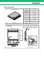
Page 37: ... 004 299 008 1 2 0 10 004 1 12 13 24 0 65 026 0 07 0 08 0 24 009 003 003 M 0 13 005 INDEX 0 17 0 03 007 001 A 0 25 010 0 10 0 10 004 004 Stand off Details of A part Mounting height 1 25 0 20 0 10 004 008 049 0 8 0 50 0 20 020 008 0 60 0 15 024 006 0 10 004 Dimensions in mm inches Note The values in parentheses are reference values Note 1 1 Resin protrusion Each side 0 15 006 Max Note 2 2 These dim...

Page 38: ...MB39A104 38 MEMO ...

Page 39: ...MB39A104 39 MEMO ...

Page 40: ... this document including descriptions of function and schematic diagrams shall not be construed as license of the use or exercise of any intellectual property right such as patent right or copyright or any other right of FUJITSU MICROELECTRONICS or any third party or does FUJITSU MICROELECTRONICS warrant non infringement of any third party s intellectual property right or other right by using such...

Reviews: