


138
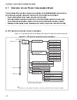
CHAPTER 6 LOW-POWER CONSUMPTION MODE
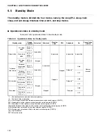
❍
Return by interrupt
The watch mode is canceled by the low-power consumption control circuit if an interrupt request
whose interrupt level is higher than 7 (other than IL2, IL1, and IL0=111
B
of the interrupt control
register (ICR)) is generated in a peripheral circuit, etc., in the watch mode. The mode
immediately changes to the sub-clock mode. After the change to the sub-clock mode, interrupts
are processed with the same method as for ordinary interrupt processing. If interrupts are
accepted by setting the I-flag of the condition code register (CCR), interrupt level mask register
(ILM), or the interrupt control register (ICR), then the CPU executes the interrupts. If an interrupt
cannot be accepted, the CPU continues processing beginning from an instruction next to the
instruction that was processed before the watch mode was set.
Note:
When executing an interrupt, an instruction next to the instruction specifying the watch mode is
normally executed first before an interrupt request is processed. If a change to the watch mode
occurs at the same time as an external bus hold request is received, an interrupt may be executed
first before the next instruction is executed.
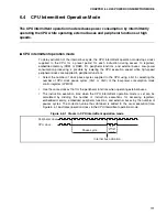
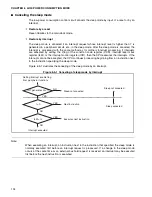
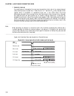
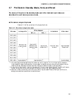
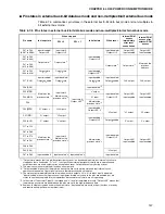
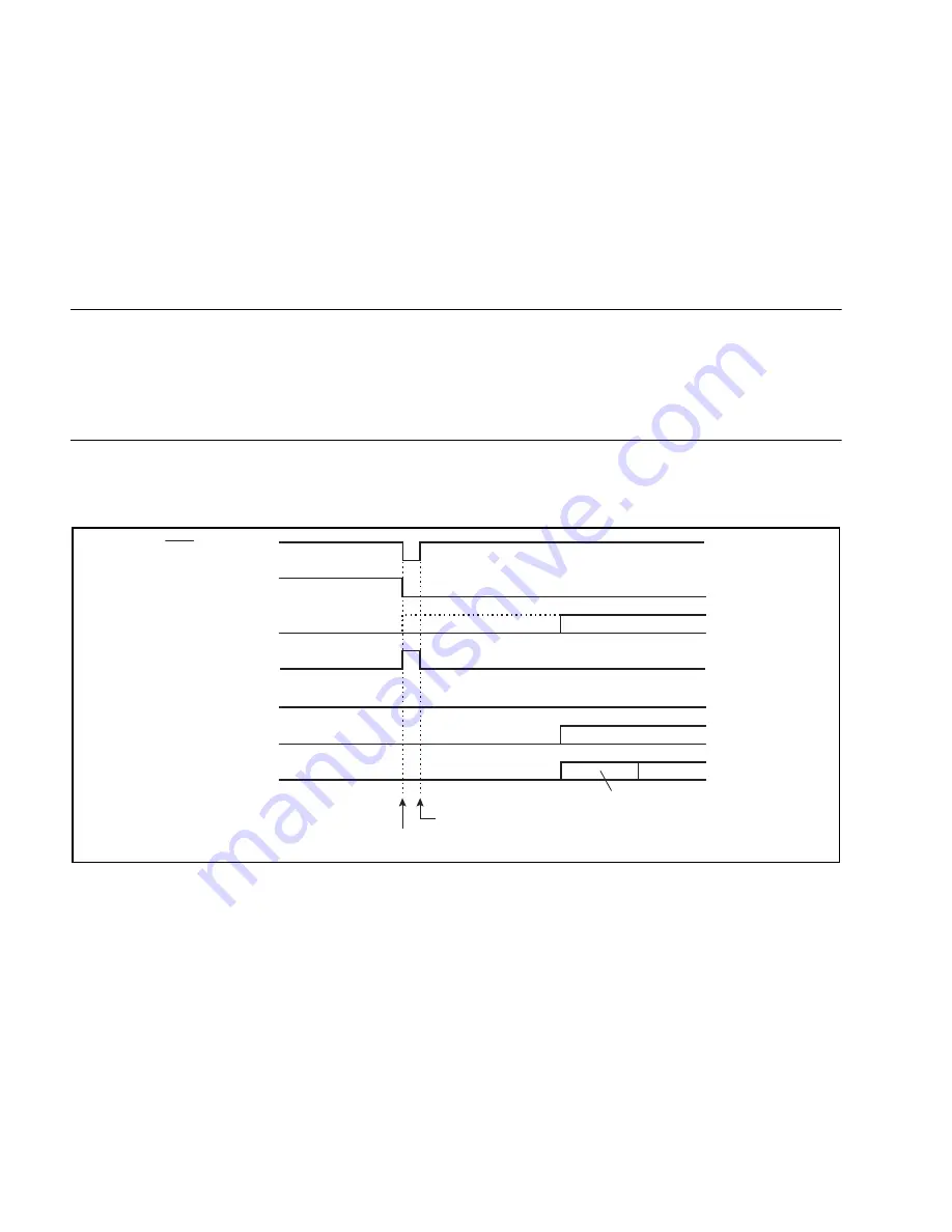
Figure 6.5-2 illustrates the cancel operation of the watch mode.
Figure 6.5-2 Cancel operation of watch mode (external reset)
RST pin
Watch mode
Main clock
PLL clock
Sub clock
CPU clock
CPU operation
Not operating
Not operating
Oscillating
Not operating
Not operating
Oscillation
Oscillation stabilization wait
During oscillation
Main clock
Processing
Sequence for resetting
Reset cancel
Watch mode cancel
Summary of Contents for MB90480 Series
Page 2: ......
Page 4: ......
Page 10: ...vi ...
Page 128: ...106 CHAPTER 4 RESET ...
Page 174: ...152 CHAPTER 6 LOW POWER CONSUMPTION MODE ...
Page 198: ...176 CHAPTER 7 MODE SETTING ...
Page 220: ...198 CHAPTER 9 TIMEBASE TIMER ...
Page 238: ...216 CHAPTER 11 WATCH TIMER ...
Page 280: ...258 CHAPTER 12 16 BIT INPUT OUTPUT TIMER ...
Page 406: ...384 CHAPTER 17 8 10 BIT A D CONVERTER ...
Page 478: ...456 CHAPTER 20 CHIP SELECTION FACILITY ...
Page 494: ...472 CHAPTER 21 ADDRESS MATCH DETECTION FUNCTION ...
Page 498: ...476 CHAPTER 22 ROM MIRROR FUNCTION SELECTION MODULE ...
Page 526: ...504 CHAPTER 23 2M 3M BIT FLASH MEMORY ...
Page 536: ...514 CHAPTER 24 EXAMPLES OF MB90F481B MB90F482B MB90F488B MB90F489B SERIAL PROGRAMMING ...
Page 570: ...548 CHAPTER 25 PWC TIMER ONLY MB90485 SERIES ...
Page 688: ......


