


139
CHAPTER 6 LOW-POWER CONSUMPTION MODE
6.5.4
Stop Mode
The stop mode stops source oscillation and stops all functions, thereby enabling
retention of data with the lowest consumption of power.
■
Change to stop mode
Write "1" in the stop mode bit (STP) of the low-power consumption mode control register
(LPMCR) to change the mode to the stop mode.
❍
Data hold function
This function in the stop mode holds data of the internal RAM and dedicated registers such as
an accumulator.
❍
Hold function
In the stop mode, the external bus hold function is stopped and hold requests cannot be
accepted even if they are input. If a hold request is input during a change to the stop mode, the
level of the HAK signal may not change to "L" while the bus is set to the high-impedance state.
❍
Operation during interrupt request
The stop mode is not set if an interrupt request is issued while "1" is set in the STP bit of the
LPMCR register.
❍
Pin state setting
Pin state specification bit (SPL) of the LPMCR register can specify whether to maintain the state
of an external pin in the stop mode in the previous state or in the high-impedance state.
■
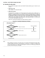
Canceling the stop mode
The low-power consumption control circuit releases the stop mode when a reset is input or an
interrupt occurs. Because the oscillation clock (HCLK) and sub-clock (SCLK) are halted, the
stop mode is released after the oscillation stabilization wait interval of the main clock or sub-
clock.
❍
Restore by a reset
When the stop mode is canceled by a reset factor, the stop mode is canceled first and the reset
state standing by for stable oscillation is set. The sequence for resetting is executed after the
end of the oscillation stabilization wait time.
Summary of Contents for MB90480 Series
Page 2: ......
Page 4: ......
Page 10: ...vi ...
Page 128: ...106 CHAPTER 4 RESET ...
Page 174: ...152 CHAPTER 6 LOW POWER CONSUMPTION MODE ...
Page 198: ...176 CHAPTER 7 MODE SETTING ...
Page 220: ...198 CHAPTER 9 TIMEBASE TIMER ...
Page 238: ...216 CHAPTER 11 WATCH TIMER ...
Page 280: ...258 CHAPTER 12 16 BIT INPUT OUTPUT TIMER ...
Page 406: ...384 CHAPTER 17 8 10 BIT A D CONVERTER ...
Page 478: ...456 CHAPTER 20 CHIP SELECTION FACILITY ...
Page 494: ...472 CHAPTER 21 ADDRESS MATCH DETECTION FUNCTION ...
Page 498: ...476 CHAPTER 22 ROM MIRROR FUNCTION SELECTION MODULE ...
Page 526: ...504 CHAPTER 23 2M 3M BIT FLASH MEMORY ...
Page 536: ...514 CHAPTER 24 EXAMPLES OF MB90F481B MB90F482B MB90F488B MB90F489B SERIAL PROGRAMMING ...
Page 570: ...548 CHAPTER 25 PWC TIMER ONLY MB90485 SERIES ...
Page 688: ......


