


227
CHAPTER 12 16-BIT INPUT/OUTPUT TIMER
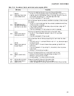
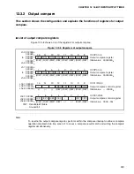
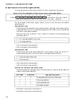
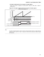
[bit5] STOP
This bit sets whether to enable or disable the counting by the free-running timer. If this bit is
set to "1", the timer stops counting, and if it is set to "0", the timer starts counting.
If the free-running timer stops counting, the output compare operation also stops.
[bit4] MODE
This bit specifies the initialization conditions of the free-running timer.
If set to "0", the reset and clear bit (bit3: SCLR) initialize the counter value.
If set to "1", in addition to the reset and clear bit (bit3: SCLR), matching the compare clear
register (CPCLR) value with the free-running timer, initializes the counter value.
The counter value initialization occurs at the point where the counter value changes.
[bit3] SCLR
This bit initializes the value of the free-running timer to "0000".
Writing "1" initializes the counter value to "0000". Writing "0" has no effect. The read value is
always "0". The counter value initialization occurs synchronizing with the counter value
change point.
If it is initialized at the time of stopping the timer, write "0000" to the data register.
Note:
After "1" is written, the counter value of this bit is not initialized to the following count clock when "0"
is written.
0
Count permit (operation) (initial value)
1
Count prohibit (stop)
0
Initialized by reset and clear bit (initial value)
1
Initialized by reset, clear bit, and compare clear register
0
No effect (initial value)
1
Initializes the counter value to "0000"
Summary of Contents for MB90480 Series
Page 2: ......
Page 4: ......
Page 10: ...vi ...
Page 128: ...106 CHAPTER 4 RESET ...
Page 174: ...152 CHAPTER 6 LOW POWER CONSUMPTION MODE ...
Page 198: ...176 CHAPTER 7 MODE SETTING ...
Page 220: ...198 CHAPTER 9 TIMEBASE TIMER ...
Page 238: ...216 CHAPTER 11 WATCH TIMER ...
Page 280: ...258 CHAPTER 12 16 BIT INPUT OUTPUT TIMER ...
Page 406: ...384 CHAPTER 17 8 10 BIT A D CONVERTER ...
Page 478: ...456 CHAPTER 20 CHIP SELECTION FACILITY ...
Page 494: ...472 CHAPTER 21 ADDRESS MATCH DETECTION FUNCTION ...
Page 498: ...476 CHAPTER 22 ROM MIRROR FUNCTION SELECTION MODULE ...
Page 526: ...504 CHAPTER 23 2M 3M BIT FLASH MEMORY ...
Page 536: ...514 CHAPTER 24 EXAMPLES OF MB90F481B MB90F482B MB90F488B MB90F489B SERIAL PROGRAMMING ...
Page 570: ...548 CHAPTER 25 PWC TIMER ONLY MB90485 SERIES ...
Page 688: ......


