


283
CHAPTER 13 8/16-BIT UP/DOWN COUNTER/TIMER
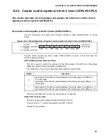
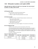
13.5.2 Writing data to up/down count register (UDCR)
Writing data directly to UDCR from a data bus is not permitted. This section includes
procedures for writing any data to UDCR.
■
Writing data to UDCR
Data can be written to UDCR with the following procedures:
1. Write the data to be written to UDCR to RCR first.
2. Writing "1" to CCRH: CTUT transfers the data from RCR to UDCR.
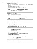
■
Clearing the counter
In addition to write "0000
H
" to UDCR, the following procedures also clear the counter.
•
Clearing with reset input (initialize)
•
Clearing with an edge input from the ZIN pin
•
Clearing by writing "0" to CCRL: UDCC
•
Clearing with the compare function
Such clear operations are is performed regardless of the occurrence for count start/stop.
■
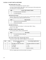
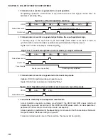
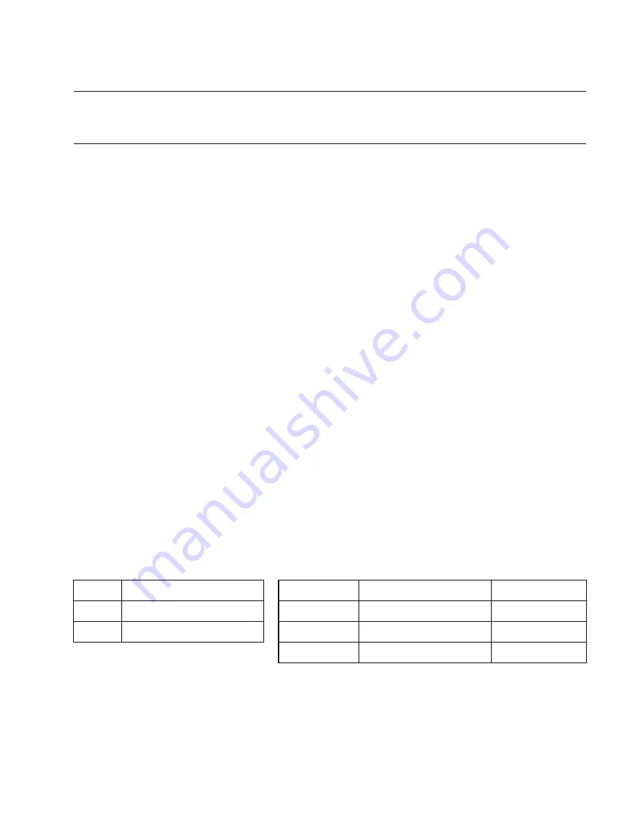
Count clear/gate function
The ZIN pin is used as either a count clear or gate function by CCRH: CGSC.
If the count clear function starts, the counter is cleared by the edge input from the ZIN pin.
CCRL: CGE1/CGE0 select the edge of the ZIN pin input signal where the counter is cleared.
When the gate function starts, the count is enabled or disabled depending on the level input
from the ZIN pin. The level of the ZIN pin input signal used to enable the count selects using
CCRL: CGE1/CGE0.
This function is available for all count modes.
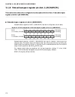
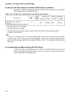
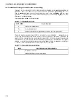
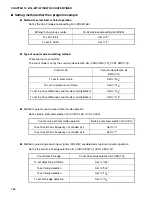
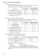
Table 13.5-4 Selection of ZIN pin function
CGSC
ZIN pin function
CGE1, CGE0
Counter clear function
Gate function
0
Counter clear function
00
B
Detect prohibited
Detect prohibited
1
Gate function
01
B
Rising edge
"L" level
10
B
Falling edge
"H" level
Summary of Contents for MB90480 Series
Page 2: ......
Page 4: ......
Page 10: ...vi ...
Page 128: ...106 CHAPTER 4 RESET ...
Page 174: ...152 CHAPTER 6 LOW POWER CONSUMPTION MODE ...
Page 198: ...176 CHAPTER 7 MODE SETTING ...
Page 220: ...198 CHAPTER 9 TIMEBASE TIMER ...
Page 238: ...216 CHAPTER 11 WATCH TIMER ...
Page 280: ...258 CHAPTER 12 16 BIT INPUT OUTPUT TIMER ...
Page 406: ...384 CHAPTER 17 8 10 BIT A D CONVERTER ...
Page 478: ...456 CHAPTER 20 CHIP SELECTION FACILITY ...
Page 494: ...472 CHAPTER 21 ADDRESS MATCH DETECTION FUNCTION ...
Page 498: ...476 CHAPTER 22 ROM MIRROR FUNCTION SELECTION MODULE ...
Page 526: ...504 CHAPTER 23 2M 3M BIT FLASH MEMORY ...
Page 536: ...514 CHAPTER 24 EXAMPLES OF MB90F481B MB90F482B MB90F488B MB90F489B SERIAL PROGRAMMING ...
Page 570: ...548 CHAPTER 25 PWC TIMER ONLY MB90485 SERIES ...
Page 688: ......


