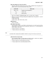

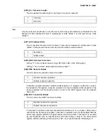


423
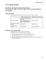
CHAPTER 19 UART
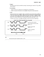
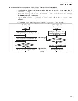
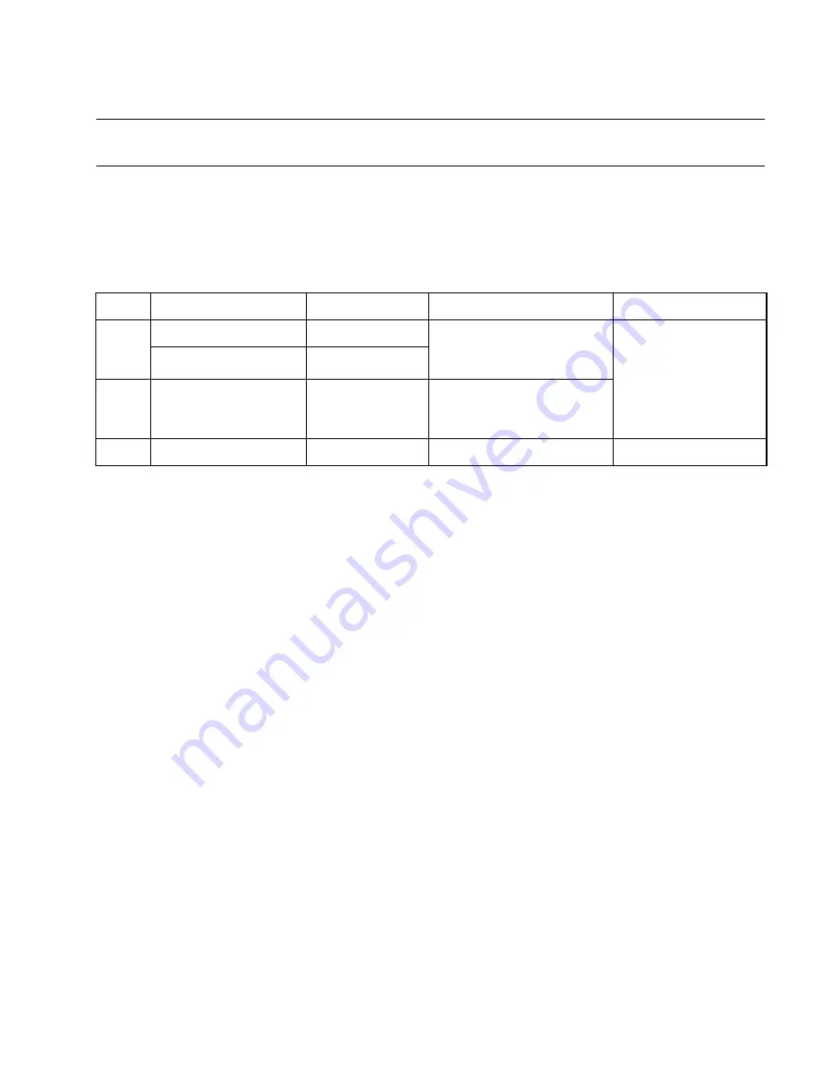
19.5 UART Operations
This section describes the operations of the UART.
■
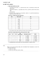
Operation modes
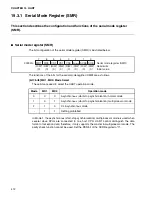
UART has the operation modes shown below. The modes can be changed by setting values in
the SMR and SCR registers.
The stop bit length in asynchronous (start-stop synchronization) mode can only be specified for
send operations. The bit length in reception operations is always one bit. Do not set the stop bit
length other than asynchronous (start-stop synchronization) mode.
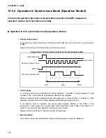
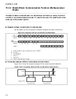
UART operation mode 1 is used only for the master in master/slave connection.
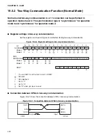
❍
Connection between CPUs
1:1 connection (normal mode) or master/slave connection (multiprocessor mode) can be
selected. The data length, whether add or not to add a parity bit and synchronization etc. for
these two systems must be the same across all CPUs. The following operation modes can be
selected:
•
In 1:1 connection (normal mode), the same operation mode, either operation mode 0 or
operation mode 2, must be selected for both CPUs.
Select operation mode 0 for asynchronous operation. Select operation mode 2 for synchronous
operation.
•
In master/slave connection (multiprocessor mode), use operation mode 1. Select operation
mode 1 and use this device as the master. For this type of connection, select "no parity".
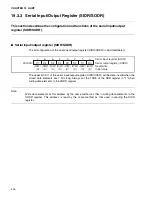
Mode
Parity
Data length
Operation mode
Stop bit length
0
Provided/not provided
7
Asynchronous (start-stop
synchronization) normal
mode
1 bit or 2 bits
*2
Provided/not provided
8
1
None
8 + 1
*1
Asynchronous (start-stop
synchronization)
multiprocessor mode
2
None
8
CLK synchronous mode
None
*1: The "+1" term represents the address/data selection bit (A/D) used in communication control.
*2: Only one bit can be detected as stop bit during reception.
Summary of Contents for MB90480 Series
Page 2: ......
Page 4: ......
Page 10: ...vi ...
Page 128: ...106 CHAPTER 4 RESET ...
Page 174: ...152 CHAPTER 6 LOW POWER CONSUMPTION MODE ...
Page 198: ...176 CHAPTER 7 MODE SETTING ...
Page 220: ...198 CHAPTER 9 TIMEBASE TIMER ...
Page 238: ...216 CHAPTER 11 WATCH TIMER ...
Page 280: ...258 CHAPTER 12 16 BIT INPUT OUTPUT TIMER ...
Page 406: ...384 CHAPTER 17 8 10 BIT A D CONVERTER ...
Page 478: ...456 CHAPTER 20 CHIP SELECTION FACILITY ...
Page 494: ...472 CHAPTER 21 ADDRESS MATCH DETECTION FUNCTION ...
Page 498: ...476 CHAPTER 22 ROM MIRROR FUNCTION SELECTION MODULE ...
Page 526: ...504 CHAPTER 23 2M 3M BIT FLASH MEMORY ...
Page 536: ...514 CHAPTER 24 EXAMPLES OF MB90F481B MB90F482B MB90F488B MB90F489B SERIAL PROGRAMMING ...
Page 570: ...548 CHAPTER 25 PWC TIMER ONLY MB90485 SERIES ...
Page 688: ......


