


522
CHAPTER 25 PWC TIMER (ONLY MB90485 SERIES)
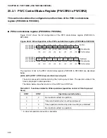
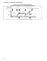
[bit11] OVIR (timer overflow interrupt request flag)
This bit is a flag used to indicate an overflow of the 16-bit up-count timer to the area from
FFFF
H
to 0000
H
. If this bit is set when timer overflow interrupt requests are enabled
(bit10:OVIE = "1"), a timer overflow interrupt request is generated.
•
Initialized to "0" at reset
•
Reading and writing are allowed; however, only writing "0" is effective, while writing "1"
causes no changes in the bit value.
•
Read-modify-write type instructions read "1" irrespective of bit values.
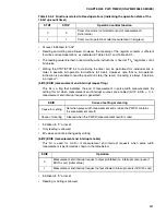
[bit10] OVIE (timer overflow interrupt request enable)
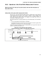
This bit is used for control of measurement end interrupt requests during pulse width
measurement, as shown in the following table.
•
Initialized to "0" at reset.
•
Reading and writing are allowed.
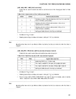
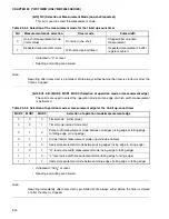
[bit9] ERR (Error Flag)
This bit is a flag that indicates that, in the repeated measurement mode of pulse width
measurement, a measurement operation has completed before the previous measurement
result was read out from the PWCR. In this case, the PWCR value will be updated to the
new measurement result while the immediately previous measurement result will be lost.
Measurement will continue irrespective of the value for this bit.
•
Initialized to "0" at reset.
•
Only reading is allowed. Write operations have no effect.
[bit8] Reserved bit
This bit is reserved.
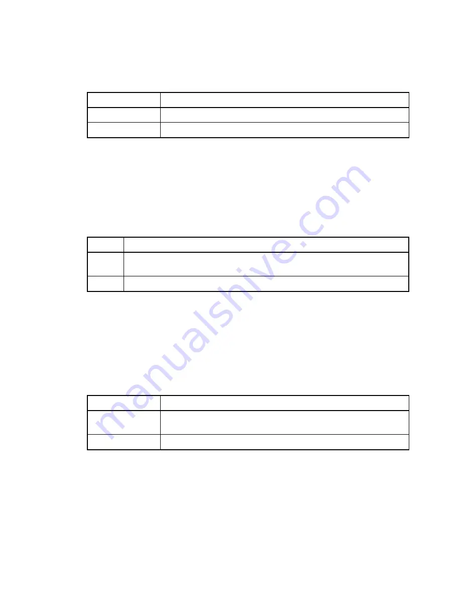
OVIR
Cause of setting or clearing
Cause for setting
Set if a timer overflow occurs (to the area from FFFF
H
to 0000
H
)
Cause of clearing
Writing "0" or clearing by
μ
DMAC
OVIE
Operation
0
Overflow interrupt request output prohibited (No interrupts occur even if OVIR is
set) [initial value]
1
Overflow interrupt request output allowed (An interrupt occurs if OVIR is set)
ERR
Cause of setting or clearing
Cause for setting
This bit is set if a measurement result that has not been read out is
overwritten by the next result.
Cause of clearing
This bit is cleared whenever the PWCR (measurement result) is read
Summary of Contents for MB90480 Series
Page 2: ......
Page 4: ......
Page 10: ...vi ...
Page 128: ...106 CHAPTER 4 RESET ...
Page 174: ...152 CHAPTER 6 LOW POWER CONSUMPTION MODE ...
Page 198: ...176 CHAPTER 7 MODE SETTING ...
Page 220: ...198 CHAPTER 9 TIMEBASE TIMER ...
Page 238: ...216 CHAPTER 11 WATCH TIMER ...
Page 280: ...258 CHAPTER 12 16 BIT INPUT OUTPUT TIMER ...
Page 406: ...384 CHAPTER 17 8 10 BIT A D CONVERTER ...
Page 478: ...456 CHAPTER 20 CHIP SELECTION FACILITY ...
Page 494: ...472 CHAPTER 21 ADDRESS MATCH DETECTION FUNCTION ...
Page 498: ...476 CHAPTER 22 ROM MIRROR FUNCTION SELECTION MODULE ...
Page 526: ...504 CHAPTER 23 2M 3M BIT FLASH MEMORY ...
Page 536: ...514 CHAPTER 24 EXAMPLES OF MB90F481B MB90F482B MB90F488B MB90F489B SERIAL PROGRAMMING ...
Page 570: ...548 CHAPTER 25 PWC TIMER ONLY MB90485 SERIES ...
Page 688: ......


