


53
CHAPTER 3 INTERRUPT
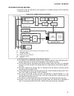
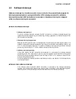
3.4
Hardware Interrupt
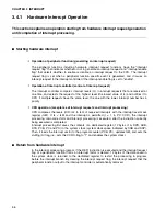
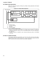
Hardware interrupt is a function to temporarily stop the execution of program being
executed by the CPU in response to an interrupt request signal from the peripheral
function. It then moves control to the interrupt processing program defined by a user.
Also,
μ
DMAC and external interrupt may be executed as a kind of hardware interrupt.
■
Hardware interrupt function
❍
Hardware interrupt function
A hardware interrupt compares the interrupt level of an interrupt request signal that is output by
the peripheral function with interrupt level mask register (ILM) in the CPU processor status (PS).
It then refers to the I-flag in the processor status (PS) to determine whether or not the interrupt
is acceptable.
If the hardware interrupt is accepted, registered contents in the CPU are automatically saved to
the system stack, and the interrupt level currently requested is stored in the interrupt level mask
register (ILM). In this event, control then branches to the corresponding interrupt vector.
❍
Multiple interrupts
Multiple hardware interrupts can start at one time.
❍
μ
DMAC
μ
DMAC is an automatic transfer function between memory and I/O, and if the transfer is
completed, a hardware interrupt starts.
μ
DMAC does not start in a multiplex manner, and if
some
μ
DMAC process is executed, other interrupt requests and all
μ
DMAC requests wait
temporarily.
❍
External interrupt
An external interrupt (including wake-up interrupt) is accepted as a hardware interrupt via the
peripheral function (interrupt request detect circuit).
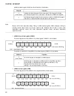
❍
Interrupt vector
Interrupt processing refers to the interrupt vector table assigned in memory addresses ranging
from FFFC00
H
to FFFFFF
H
and shared with software interrupts.
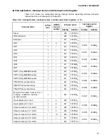
For the assignment of interrupt number and interrupt vector, see Section "3.2 Interrupt Factor
and Interrupt Vector".
Summary of Contents for MB90480 Series
Page 2: ......
Page 4: ......
Page 10: ...vi ...
Page 128: ...106 CHAPTER 4 RESET ...
Page 174: ...152 CHAPTER 6 LOW POWER CONSUMPTION MODE ...
Page 198: ...176 CHAPTER 7 MODE SETTING ...
Page 220: ...198 CHAPTER 9 TIMEBASE TIMER ...
Page 238: ...216 CHAPTER 11 WATCH TIMER ...
Page 280: ...258 CHAPTER 12 16 BIT INPUT OUTPUT TIMER ...
Page 406: ...384 CHAPTER 17 8 10 BIT A D CONVERTER ...
Page 478: ...456 CHAPTER 20 CHIP SELECTION FACILITY ...
Page 494: ...472 CHAPTER 21 ADDRESS MATCH DETECTION FUNCTION ...
Page 498: ...476 CHAPTER 22 ROM MIRROR FUNCTION SELECTION MODULE ...
Page 526: ...504 CHAPTER 23 2M 3M BIT FLASH MEMORY ...
Page 536: ...514 CHAPTER 24 EXAMPLES OF MB90F481B MB90F482B MB90F488B MB90F489B SERIAL PROGRAMMING ...
Page 570: ...548 CHAPTER 25 PWC TIMER ONLY MB90485 SERIES ...
Page 688: ......


