78
CHAPTER 3 INTERRUPT
3.7
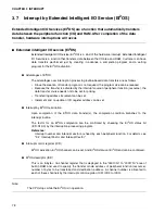
Interrupt by Extended Intelligent I/O Service (EI
2
OS)
Extended Intelligent I/O Services (EI
2
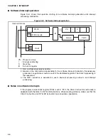
OS) are a function that automatically transfers
data between the peripheral function (I/O) and RAM. After completion of the data
transfer, hardware interruptions will occur.
■
Extended intelligent I/O service (EI
2
OS)
Extended Intelligent I/O Service (EI
2
OS) is a kind of the hardware interrupt. Extended Intelligent
I/O Service is a function that transfers data between the I/O area and RAM. Customer can have
data transfers performed just by creating in advance a completion program and a setting
program for the EI
2
OS activation.
●
Advantages of EI
2
OS
The advantages over interruption processing routine-based data transfers are as follows:
•
Since the creation of transfer program is not required, the program size can be reduced.
•
Because the transfer is activated by the interrupt source of peripheral function (resource), the
data transfer source needs not to be set for polling.
•
Transferring address increment can be set.
•
Increment and no update of I/O register address ca be set.
●
Interrupt by EI
2
OS termination
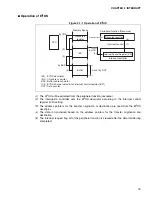
Upon completion of the EI
2
OS data transfer(s), the completion condition branches to the
interrupt routine.
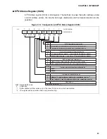
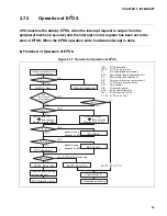
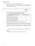
The factor for an EI
2
OS completion can be confirmed by checking the EI
2
OS status bit
(ICR:S1,S0) by the interruption processing program.
Reference:
Interrupt number and interrupt vector are fixed by each peripheral function. For details, see
"3.2 Interrupt Factor and Interrupt Vector".
●
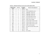
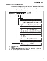
Interrupt control register (ICR)
EI
2
OS activation, EI
2
OS channel can be set. And EI
2
OS status at EI
2
OS end can be confirmed.
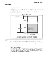
●
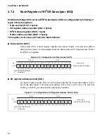
EI
2
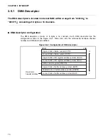
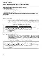
OS descriptor (ISD)
This is an 8-byte
×
16-channel register that is deployed in the “000100
H
” to “00017F
H
” area of
built-in RAM and used to specify the transfer mode, address of peripheral function (resource),
number of bytes to be transferred and destination address. A channel number is allocated to
each of these channels by the interrupt control register (ICR: ICS3 to ICS0).
Note:
The CPU stops while the EI
2
OS is in operation.
Summary of Contents for MB90480 Series
Page 2: ......
Page 4: ......
Page 10: ...vi ...
Page 128: ...106 CHAPTER 4 RESET ...
Page 174: ...152 CHAPTER 6 LOW POWER CONSUMPTION MODE ...
Page 198: ...176 CHAPTER 7 MODE SETTING ...
Page 220: ...198 CHAPTER 9 TIMEBASE TIMER ...
Page 238: ...216 CHAPTER 11 WATCH TIMER ...
Page 280: ...258 CHAPTER 12 16 BIT INPUT OUTPUT TIMER ...
Page 406: ...384 CHAPTER 17 8 10 BIT A D CONVERTER ...
Page 478: ...456 CHAPTER 20 CHIP SELECTION FACILITY ...
Page 494: ...472 CHAPTER 21 ADDRESS MATCH DETECTION FUNCTION ...
Page 498: ...476 CHAPTER 22 ROM MIRROR FUNCTION SELECTION MODULE ...
Page 526: ...504 CHAPTER 23 2M 3M BIT FLASH MEMORY ...
Page 536: ...514 CHAPTER 24 EXAMPLES OF MB90F481B MB90F482B MB90F488B MB90F489B SERIAL PROGRAMMING ...
Page 570: ...548 CHAPTER 25 PWC TIMER ONLY MB90485 SERIES ...
Page 688: ......


