121
CHAPTER 5 CLOCKS
5.5
Oscillation Stabilization Wait Time
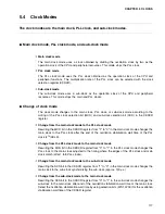
When the power is turned on, when stop mode is released, or switching from the sub-
clock to the main clock or from sub-clock to the PLL clock occurs, an oscillation
stabilization wait time is required after oscillation begins because the oscillation clock
is stopped. When switching from the main clock to the PLL clock or from the main
clock to the sub-clock occurs, an oscillation stabilization wait time is required.
■
Oscillation stabilization wait time
Ceramic and crystal oscillators generally require a waiting time ranging from several
milliseconds to several ten milliseconds after the start of oscillation until oscillation stabilizes to a
natural frequency (oscillation frequency). Therefore, disable CPU operation immediately after
the start of oscillation, and supply a clock to the CPU when oscillation completely stabilizes
following the elapse of the oscillation stabilization wait time. Specify a oscillation stabilization
wait time suitable for the oscillator used because the time required for oscillation to stabilize
varies depending on the type of oscillator (crystal, ceramic, or other material). The oscillation
stabilization wait time can be selected by defining the clock selection register (CKSCR).
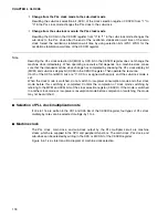
When the clock mode is switched from the main clock to the PLL clock, the main clock to the
subclock, the subclock to the main clock, or the subclock to the PLL clock, the CPU runs in the
clock mode set before switching. After the oscillation stabilization wait time, the CPU changes
to the selected clock mode.
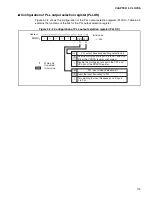
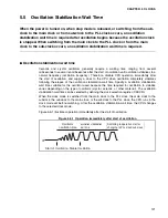
Figure 5.5-1 illustrates operation immediately after the start of oscillation.
Figure 5.5-1 Operation immediately after start of oscillation
Start of Oscillation Stable Oscillation
Oscillator
oscillation time
oscillation stabilization
wait time
Switching to operation start or
changing to PLL clock/sub clock
X1
Summary of Contents for MB90480 Series
Page 2: ......
Page 4: ......
Page 10: ...vi ...
Page 128: ...106 CHAPTER 4 RESET ...
Page 174: ...152 CHAPTER 6 LOW POWER CONSUMPTION MODE ...
Page 198: ...176 CHAPTER 7 MODE SETTING ...
Page 220: ...198 CHAPTER 9 TIMEBASE TIMER ...
Page 238: ...216 CHAPTER 11 WATCH TIMER ...
Page 280: ...258 CHAPTER 12 16 BIT INPUT OUTPUT TIMER ...
Page 406: ...384 CHAPTER 17 8 10 BIT A D CONVERTER ...
Page 478: ...456 CHAPTER 20 CHIP SELECTION FACILITY ...
Page 494: ...472 CHAPTER 21 ADDRESS MATCH DETECTION FUNCTION ...
Page 498: ...476 CHAPTER 22 ROM MIRROR FUNCTION SELECTION MODULE ...
Page 526: ...504 CHAPTER 23 2M 3M BIT FLASH MEMORY ...
Page 536: ...514 CHAPTER 24 EXAMPLES OF MB90F481B MB90F482B MB90F488B MB90F489B SERIAL PROGRAMMING ...
Page 570: ...548 CHAPTER 25 PWC TIMER ONLY MB90485 SERIES ...
Page 688: ......

