196
CHAPTER 9 TIMEBASE TIMER
9.6
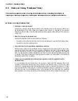
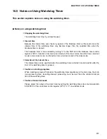
Notes on Using Timebase Timer
This section explains notes on using the timebase timer, including the effects of
clearing an interrupt request or clearing the timebase timer on peripheral functions.
■
Notes on using timebase timer
❍
Clearing an interrupt request
Clearing the interrupt request flag bit (TBOF) of the timebase timer control register (TBTC) must
be implemented in the state where the timebase timer interrupt is masked by the interrupt
request permit bit (TBIE) or by the interrupt level mask register (ILM) setting of the processor
status (PS).
❍
Effect of clearing the timebase timer
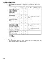
Clearing the timebase timer counter affects the following:
•
Operations where the interval timer function (interval interrupt) is used by the timebase timer
•
Operations using the watchdog timer
❍
Use of the timer for the oscillation stabilization wait time
When power is turned on, the oscillation clock is stopped in the main stop mode. In such a case,
after the oscillator starts operating, the oscillation stabilization wait time of the oscillation clock
must be provided by using as a timing reference the operation clock supplied by the timebase
timer. An appropriate oscillation stabilization wait time must be selected depending on the type
of oscillator (resonator) connected to the high-speed oscillation pin. See Section "5.5 Oscillation
Stabilization Wait Time", for details.
❍
Caution on using peripheral functions whose operation clock is supplied from the
timebase timer
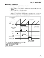
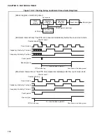
In a mode where the main clock stops, the counter is cleared and the timebase timer stops
operating. Furthermore, because the clock supplied by the timebase timer is reset to the initial
state and is supplied again when the timebase timer counter is cleared, the period of "H" level
may become shorter or the period of "L" level may become longer by a maximum of a 1/2 cycle.
Although the clock for the watchdog timer is also supplied from the initial state, the watchdog
timer operates at normal cycles because the watchdog time counter is cleared at the same time.
Summary of Contents for MB90480 Series
Page 2: ......
Page 4: ......
Page 10: ...vi ...
Page 128: ...106 CHAPTER 4 RESET ...
Page 174: ...152 CHAPTER 6 LOW POWER CONSUMPTION MODE ...
Page 198: ...176 CHAPTER 7 MODE SETTING ...
Page 220: ...198 CHAPTER 9 TIMEBASE TIMER ...
Page 238: ...216 CHAPTER 11 WATCH TIMER ...
Page 280: ...258 CHAPTER 12 16 BIT INPUT OUTPUT TIMER ...
Page 406: ...384 CHAPTER 17 8 10 BIT A D CONVERTER ...
Page 478: ...456 CHAPTER 20 CHIP SELECTION FACILITY ...
Page 494: ...472 CHAPTER 21 ADDRESS MATCH DETECTION FUNCTION ...
Page 498: ...476 CHAPTER 22 ROM MIRROR FUNCTION SELECTION MODULE ...
Page 526: ...504 CHAPTER 23 2M 3M BIT FLASH MEMORY ...
Page 536: ...514 CHAPTER 24 EXAMPLES OF MB90F481B MB90F482B MB90F488B MB90F489B SERIAL PROGRAMMING ...
Page 570: ...548 CHAPTER 25 PWC TIMER ONLY MB90485 SERIES ...
Page 688: ......

