200
CHAPTER 10 WATCHDOG TIMER
10.1 Overview of Watchdog Timer
The watchdog timer is a 2-bit counter that uses the output of the timebase timer or the
watch timer as the count clock, and if it is not cleared within a certain period of time
after startup, this timer resets the CPU.
■
Functions of watchdog timer
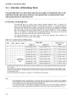
The watchdog timer is a counter used to prevent runaway programs. Once it is started, this
timer must be cleared periodically within a certain period of time. If it is not cleared within a
certain period of time because a program is running in an infinite loop, it generates a watchdog
reset to the CPU. The interval time of the watchdog timer can be specified on the WT1 and WT0
bits in the watchdog timer control register (WDTC), as shown in Table 10.1-1. If the watchdog
timer is not cleared, a watchdog reset is generated between the minimum time and the
maximum time. Be sure to clear the timer within the minimum time.
The output destination of the clock source is set by the watchdog clock selection bit
(WTC:WDCS) of the clock timer control register.
Note:
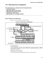
The watchdog counter is composed of a 2-bit counter to count the carry signals of the timebase
timer. Therefore, if the timebase timer counter has been cleared, the time until the occurrence of
watchdog reset may become longer than the specified time.
To use the sub-clock as a machine clock, please select the output of the clock timer by setting the
watchdog timer clock source selection bit (WDCS) of the clock timer control register (WTC) to "0".
Table 10.1-1 Interval time for watchdog timer
WT1
WT0
WDCS
SCM
Interval time
Number of clock
cycles
Minimum *
Maximum *
0
0
1
1
Approximately 3.58 ms
Approximately 4.61 ms
(2
14
±
2
11
)/HCLK cycles
0
1
1
1
Approximately 14.33 ms
Approximately 18.43 ms
(2
16
±
2
13
)/HCLK cycles
1
0
1
1
Approximately 57.23 ms
Approximately 73.73 ms
(2
18
±
2
15
)/HCLK cycles
1
1
1
1
Approximately 458.75 ms
Approximately 589.82 ms
(2
21
±
2
18
)/HCLK cycles
0
0
Combination
other than the
above
Approximately 0.457 s
Approximately 0.576 s
(2
12
±
2
9
)/SCLK cycles
0
1
Approximately 3.584 s
Approximately 4.608 s
(2
15
±
2
12
)/SCLK cycles
1
0
Approximately 7.168 s
Approximately 9.216 s
(2
16
±
2
13
)/SCLK cycles
1
1
Approximately 14.336 s
Approximately 18.432 s
(2
17
±
2
14
)/SCLK cycles
*: Values during operation of the oscillation clock (HCLK) at 4 MHz and the sub-clock (SCLK) at 32 kHz frequency divided
by 4 (= 8 kHz)
The maximum and minimum watchdog timer interval times and the number of the oscillation clock cycles depend on the
timing of the clear operation. The interval time is 3.5 to 4.5 times as large as the cycle of the count clock (clock supplied
by the timebase timer).
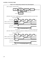
For the watchdog timer interval times, see Section "10.4 Watchdog Timer Operation".
Summary of Contents for MB90480 Series
Page 2: ......
Page 4: ......
Page 10: ...vi ...
Page 128: ...106 CHAPTER 4 RESET ...
Page 174: ...152 CHAPTER 6 LOW POWER CONSUMPTION MODE ...
Page 198: ...176 CHAPTER 7 MODE SETTING ...
Page 220: ...198 CHAPTER 9 TIMEBASE TIMER ...
Page 238: ...216 CHAPTER 11 WATCH TIMER ...
Page 280: ...258 CHAPTER 12 16 BIT INPUT OUTPUT TIMER ...
Page 406: ...384 CHAPTER 17 8 10 BIT A D CONVERTER ...
Page 478: ...456 CHAPTER 20 CHIP SELECTION FACILITY ...
Page 494: ...472 CHAPTER 21 ADDRESS MATCH DETECTION FUNCTION ...
Page 498: ...476 CHAPTER 22 ROM MIRROR FUNCTION SELECTION MODULE ...
Page 526: ...504 CHAPTER 23 2M 3M BIT FLASH MEMORY ...
Page 536: ...514 CHAPTER 24 EXAMPLES OF MB90F481B MB90F482B MB90F488B MB90F489B SERIAL PROGRAMMING ...
Page 570: ...548 CHAPTER 25 PWC TIMER ONLY MB90485 SERIES ...
Page 688: ......

