235
CHAPTER 12 16-BIT INPUT/OUTPUT TIMER
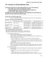
12.4 Interrupt of 16-bit Input/Output Timer
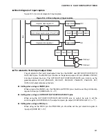
The interrupt request of the 16-bit input/output timer occurs for three following.
• The counter value of the free-running timer overflows.
• The trigger edge input to the input capture input pin is performed.
• A match with the output compare is detected.
The DMA transfer and extended intelligent I/O service (EI
2
OS) can be activated for the
interrupt of the input capture and output compare.
■
Interrupt of 16-bit input/output timer
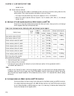
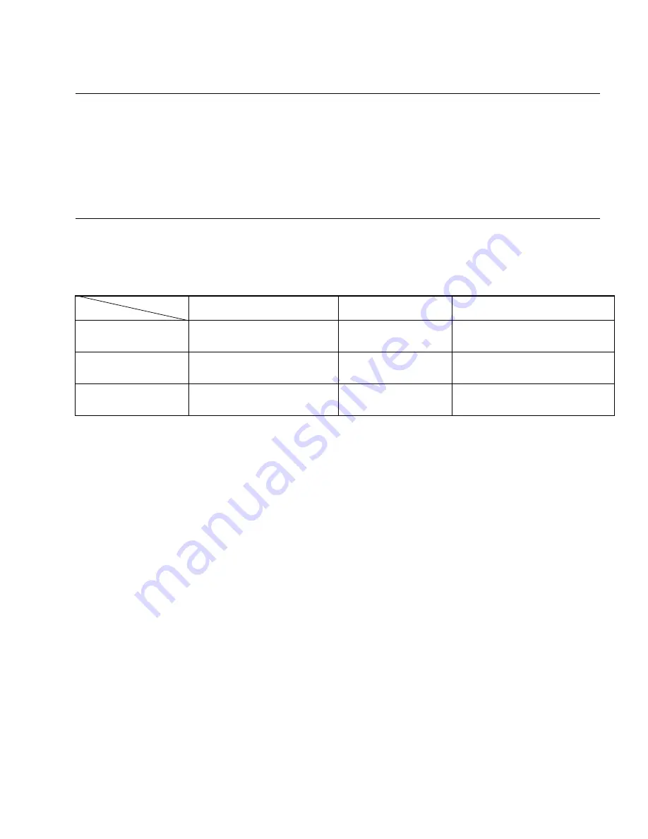
Table 12.4-1 shows the interrupt control bit and interrupt source of the 16-bit input/output timer.
●
Timer counter overflow interrupt
When the timer counter overflow interrupt request flag is set
The timer counter overflow generation flag in the timer counter control status register is set
when the followings occur (TCCS: IVF=1)
•
When an overflow ("FFFF
H
"
→
"0000
H
") occurs in counting up of the free-running timer
•
When the initialization by compare clear register is set to enable (TCCS: MODE=1) and an
match between the setting value of the free-running timer and the value of the compare clear
register occurs.
When the timer counter overflow interrupt request occurs
If the timer counter overflow interrupt request is set to enable (TCCS: IVFE=1), the interrupt
request is generated when the timer counter overflow generation flag is set to 1 (TCCS: IVF=1).
●
Input capture interrupt
The interrupt operation when the valid edge (ICS: EG) set by the input capture pin is detected is
shown as follows :
•
The count value of the free-running timer upon detection is stored in the input capture
register.
•
The valid edge detection flag in the control status register is set to 1 (ICS: ICP=1).
•
When the input capture interrupt request output is set to enable (ICS: ICE=1), the interrupt
Table 12.4-1 Interrupt of 16-bit input/output timer
Timer counter overflow interrupt
Input capture interrupt
Output compare interrupt
Interrupt request flag
TCCS: IVF (bit7)
ICS01: ICP1 (bit7) ch.1
ICS01: ICP0 (bit6) ch.0
OCS01/23/45: ICP1 (bit7) ch.1,3,5
OCS01/23/45: ICP0 (bit6) ch.0,2,4
Interrupt request output
enable bit
TCCS: IVFE (bit6)
ICS01: ICE1 (bit5) ch.1
ICS01: ICE0 (bit4) ch.0
OCS01/23/45: ICE1 (bit5) ch.1,3,5
OCS01/23/45: ICE0 (bit4) ch.0,2,4
Interrupt generation
source
Counter overflow of 16-bit
free-running timer
Valid edge input to input
capture input pin
Match between output compare
register value and counter value
ICS01: ICP0/ICE0 correspond to input capture pin (IN0).
ICS01: ICP1/ICE1 correspond to input capture pin (IN0).
OCS01/23/45: ICP0/ICE0 correspond to output compare pins (OUT0/OUT2/OUT4).
OCS01/23/45: ICP1/ICE1 correspond to output compare pins (OUT1/OUT3/OUT5).
Summary of Contents for MB90480 Series
Page 2: ......
Page 4: ......
Page 10: ...vi ...
Page 128: ...106 CHAPTER 4 RESET ...
Page 174: ...152 CHAPTER 6 LOW POWER CONSUMPTION MODE ...
Page 198: ...176 CHAPTER 7 MODE SETTING ...
Page 220: ...198 CHAPTER 9 TIMEBASE TIMER ...
Page 238: ...216 CHAPTER 11 WATCH TIMER ...
Page 280: ...258 CHAPTER 12 16 BIT INPUT OUTPUT TIMER ...
Page 406: ...384 CHAPTER 17 8 10 BIT A D CONVERTER ...
Page 478: ...456 CHAPTER 20 CHIP SELECTION FACILITY ...
Page 494: ...472 CHAPTER 21 ADDRESS MATCH DETECTION FUNCTION ...
Page 498: ...476 CHAPTER 22 ROM MIRROR FUNCTION SELECTION MODULE ...
Page 526: ...504 CHAPTER 23 2M 3M BIT FLASH MEMORY ...
Page 536: ...514 CHAPTER 24 EXAMPLES OF MB90F481B MB90F482B MB90F488B MB90F489B SERIAL PROGRAMMING ...
Page 570: ...548 CHAPTER 25 PWC TIMER ONLY MB90485 SERIES ...
Page 688: ......

