338
CHAPTER 15 8/16-BIT PPG TIMER
15.6
Program Example of 8/16-Bit PPG Timer
This section describes the program example of the 8/16-bit PPG timer.
■
Program Example of 8/16-bit PPG Timer
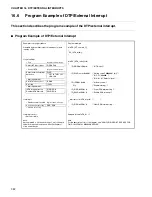
Example of setting procedure
Generate interval interrupt and output PPG.
(PPG output from PPG1 pin, software trigger)
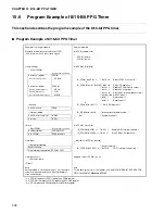
Program example
void PPG_sample(void)
{
PPG01_initial();
PPG01_start();
}
<Initial setting>
•
Set duty
•
Interrupt related
void PPG01_initial(void)
{
*1
IO_PPG01.bit.PCS = 1;
/* bit7-5 = 0
Select PPG1 count clock */
*2
IO_PPGC01.word = 0x3101;/* bit15 = 0
Stop PPG operation */
/* bit13 = 1
Enable PPG1/3/5 pulse output */
/* bit12 = 1
Enable PPG interrupt */
/* bit11 = 0
Clear PUF1 interrupt request flag */
/* bit10-9 = 00 8-bit PPG 2ch */
/* bit8 = 1
Reserved bit */
/* bit0 = 1
Reserved bit */
*3
IO_PRL0.word = 0x7f7f;
/* Set PPG duty ratio */
IO_ICR05.byte = 0x10;
/* Interrupt level (arbitrary value) */
__EI();
/* Enable interrupt */
}
<Start>
void PPG01_start(void)
{
IO_PPGC01.bit.PIE1 = 1; /* bit12= 1
Enable PIE1 interrupt request */
IO_PPGC01.bit.PEN1 = 1; /* bit15 = 1
Start PEN1 PPG operation */
}
<Interrupt>
__interrupt void PPG01_int(void)
{
/* Any processing */
IO_PPGC01.bit.PUF1 = 0; /* bit11 = 0
PUF1 interrupt request flag */
}
<Interrupt vector>
•
Set vector table
<Other>
#pragma intvect PPG01_int 22
Note:
Setting related to clock and setting of _set_il (numeric
value) are required in advance. See the chapter of
clock and interrupt.
Note:
For the description form of the register, see "SAMPLE I/O REGISTER FILES FOR
F
2
MC-16LX FAMILY MB90480 SERIES".
*1: io_PPG01 represents PPG1 register and PPG0 register.
*2: io_PPGC01 represents PPGC1 register and PPGC0 register.
*3: io_PRL0 represents PRLL0 register and PRLH0 register.
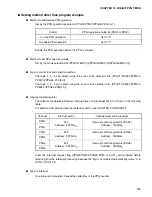
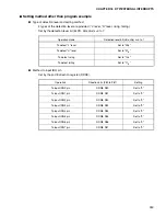
•
Control PPG01
Register name. bit name
Set control register
PPG01
Select count clock >>
.PCS2-0
Set control register
PPGC01
Enable pulse output >>
.PE10
Enable interrupt >>
.PIE1
Select operation mode >>
.MD1-0
Set PPG01 duty
PRL0
Set PPG01 interrupt level
ICR05
Set I flag
(CCR)
•
Start PPG01
Register name. bit name
Enable interrupt
PPGC01.PIE1
Start PPG01
PPGC01.PEN1
•
Interrupt processing
Any processing
Clear interrupt request flag PPGC01.PUF1
Summary of Contents for MB90480 Series
Page 2: ......
Page 4: ......
Page 10: ...vi ...
Page 128: ...106 CHAPTER 4 RESET ...
Page 174: ...152 CHAPTER 6 LOW POWER CONSUMPTION MODE ...
Page 198: ...176 CHAPTER 7 MODE SETTING ...
Page 220: ...198 CHAPTER 9 TIMEBASE TIMER ...
Page 238: ...216 CHAPTER 11 WATCH TIMER ...
Page 280: ...258 CHAPTER 12 16 BIT INPUT OUTPUT TIMER ...
Page 406: ...384 CHAPTER 17 8 10 BIT A D CONVERTER ...
Page 478: ...456 CHAPTER 20 CHIP SELECTION FACILITY ...
Page 494: ...472 CHAPTER 21 ADDRESS MATCH DETECTION FUNCTION ...
Page 498: ...476 CHAPTER 22 ROM MIRROR FUNCTION SELECTION MODULE ...
Page 526: ...504 CHAPTER 23 2M 3M BIT FLASH MEMORY ...
Page 536: ...514 CHAPTER 24 EXAMPLES OF MB90F481B MB90F482B MB90F488B MB90F489B SERIAL PROGRAMMING ...
Page 570: ...548 CHAPTER 25 PWC TIMER ONLY MB90485 SERIES ...
Page 688: ......

