348
CHAPTER 16 DTP/EXTERNAL INTERRUPTS
16.4 Operations of DTP/External Interrupt Unit
This section describes the operations of the DTP/external interrupt unit.
■
Operation of external interrupt unit
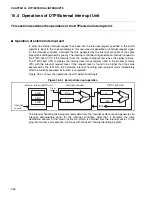
If, after an external interrupt request has been set, the interrupt request specified in the ELVR
register is input to the corresponding pin, this resource will generate an interrupt request signal
for the interrupt controller. Interrupts that are generated by the interrupt controller at the same
time will be distinguished by priority. The interrupt controller will generate an interrupt request to
the F
2
MC-16LX CPU if the interrupt from the corresponding resource has the highest priority.
The F
2
MC-16LX CPU compares the interrupt level mask register (ILM) in the processor status
(PS) with the interrupt request level. If the request level is found to be higher than the value
expressed by the ILM bits, the hardware interrupt handling microprogram starts immediately
after the currently executed instruction is completed.
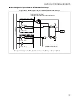
Figure 16.4-1 shows the operational flow for external interrupts.
Figure 16.4-1 External interrupt operation
The interrupt handling microprogram reads data from the interrupt vector area and generates an
interrupt acknowledge signal for the interrupt controller. After that, it transfers the jump
destination address of the macro instruction, which is obtained from the interrupt vector, to the
program counter, and execution continues with the user's interrupt handling program.
External interrupt/DTP unit
Interrupt controller
F
2
MC-16LXCPU
Other
request
ELVR
EIRR
ENIR
Interrupt
source
CMP
CMP
ICR
yy
ICF
xx
IL
ILM
INTA
Summary of Contents for MB90480 Series
Page 2: ......
Page 4: ......
Page 10: ...vi ...
Page 128: ...106 CHAPTER 4 RESET ...
Page 174: ...152 CHAPTER 6 LOW POWER CONSUMPTION MODE ...
Page 198: ...176 CHAPTER 7 MODE SETTING ...
Page 220: ...198 CHAPTER 9 TIMEBASE TIMER ...
Page 238: ...216 CHAPTER 11 WATCH TIMER ...
Page 280: ...258 CHAPTER 12 16 BIT INPUT OUTPUT TIMER ...
Page 406: ...384 CHAPTER 17 8 10 BIT A D CONVERTER ...
Page 478: ...456 CHAPTER 20 CHIP SELECTION FACILITY ...
Page 494: ...472 CHAPTER 21 ADDRESS MATCH DETECTION FUNCTION ...
Page 498: ...476 CHAPTER 22 ROM MIRROR FUNCTION SELECTION MODULE ...
Page 526: ...504 CHAPTER 23 2M 3M BIT FLASH MEMORY ...
Page 536: ...514 CHAPTER 24 EXAMPLES OF MB90F481B MB90F482B MB90F488B MB90F489B SERIAL PROGRAMMING ...
Page 570: ...548 CHAPTER 25 PWC TIMER ONLY MB90485 SERIES ...
Page 688: ......

