MB95630H Series
MN702-00009-1v0-E
FUJITSU SEMICONDUCTOR LIMITED
105
CHAPTER 8 HARDWARE/SOFTWARE WATCHDOG TIMER
8.3 Operations and Setting Procedure
Example
■
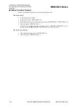
Setting Procedure Example
Below is the procedure for setting the software watchdog timer.
1. Select the count clock. (WDTC:CS[1:0], CSP)
2. Activate the watchdog timer. (WDTC:WTE[3:0] = 0b0101)
3. Clear the watchdog timer. (WDTC:WTE[3:0] = 0b0101)
Below is the procedure for setting the hardware watchdog timer.
1. Write any value except "0xA596" to the addresses 0xFFBE and 0xFFBF on the Flash
memory. After a reset, the data in 0xFFBE and 0xFFBF
on the Flash memory are copied to
the watchdog timer selection ID register (upper/lower) (WDTH/WDTL) (0x0FEB/
0x0FEC). Writing "0xA597" to the addresses 0xFFBE and 0xFFBF on the Flash memory
enables the hardware watchdog timer except in standby modes; writing any value other than
"0xA596" and "0xA597" enables the hardware watchdog timer in all modes. See
"CHAPTER 26 NON-VOLATILE REGISTER (NVR) INTERFACE" for details of the
watchdog timer selection ID.
2. Clear the watchdog timer. (WDTC:WTE[3:0] = 0b0101)


