MB95630H Series
MN702-00009-1v0-E
FUJITSU SEMICONDUCTOR LIMITED
147
CHAPTER 11 8/16-BIT COMPOSITE TIMER
11.7 Operation of Interval Timer Function
(Continuous Mode)
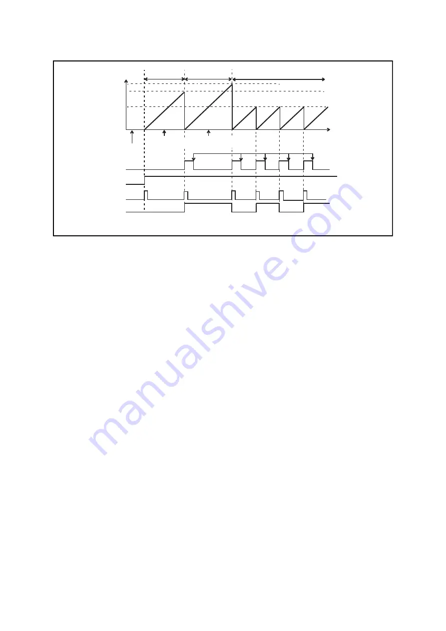
Figure 11.7-2 Operation Diagram of Interval Timer Function (Continuous Mode)
Comp
a
re v
a
l
u
e
Comp
a
re v
a
l
u
e
(0xFF)
Comp
a
re v
a
l
u
e
(0x
8
0)
0xFF
0x
8
0
0x00
Tn0DR/Tn1DR v
a
l
u
e (0xE0)
Cle
a
red
b
y progr
a
m
Time
IF
b
it
S
TA
b
it
Co
u
nter cle
a
r
*2
Timer o
u
tp
u
t pin
*1: If the Tn0DR/Tn1DR d
a
t
a
regi
s
ter v
a
l
u
e i
s
modified d
u
ring oper
a
tion, the new v
a
l
u
e i
s
us
ed from the next
a
ctive cycle.
0xE0
Comp
a
re v
a
l
u
e
(0xE0)
Activ
a
ted
M
a
tched
M
a
tched
M
a
tched
M
a
tched
M
a
tched
*2: The co
u
nter i
s
cle
a
red
a
nd the d
a
t
a
regi
s
ter
s
etting
s
a
re lo
a
ded into the comp
a
ri
s
on d
a
t
a
l
a
tch whenever
a
m
a
tch i
s
detected d
u
ring oper
a
tion.
Tn0DR/Tn1DR v
a
l
u
e
modified (0xFF
→
0x
8
0)*1
Tn0DR/Tn1DR
v
a
l
u
e modified
(0xE0
→
0xFF)*1


