MB95630H Series
MN702-00009-1v0-E
FUJITSU SEMICONDUCTOR LIMITED
201
CHAPTER 14 LIN-UART
14.2 Configuration
■
Block Diagram of LIN-UART
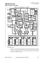
Figure 14.2-1 Block Diagram of LIN-UART
●
Reload counter
This block is a 15-bit reload counter functioning as a dedicated baud rate generator. The block
consists of a 15-bit register for reload values; it generates the transmit/receive clock from the
external or internal clock. The count value in the transmit reload counter is read from the baud
rate generator1, 0 (BGR1 and BGR0).
RDR
TDR
PEN
P
S
BL
CL
AD
CRE
RXE
TXE
MD1
MD0
OTO
EXT
RE
S
T
S
CKE
S
OE
PE
ORE
FRE
RDRF
TDRE
BD
S
RIE
TIE
LBIE
LBD
S
OPE
S
IOP
CCO
S
CE
S
LBIE
LBD
RBI
RIE
TIE
IRQ
IRQ
LBD
S
IN
PE
ORE FRE
M
a
chine
clock
S
IN
S
OT
M
S
SS
M
S
CDE
TDRE
RDRF
RBI
TBI
UPCL
OTO,
EXT,
RE
S
T
PE
ORE
FRE
TBI
RBI
TBI
S
IN
S
CK
S
OT
LBR
LBR
LBL1
LBL0
LBL1
LBL0
Pin
Pin
Pin
Relo
a
d
co
u
nter
Re
s
t
a
rt receive
relo
a
d co
u
nter
Over-
sa
mpling
circ
u
it
Intern
a
l
s
ign
a
l
to
8
/16-
b
it
compo
s
ite timer
LIN
b
re
a
k/
S
ynField
detection
circ
u
it
Error
detection
Intern
a
l d
a
t
a
bus
SS
R
regi
s
ter
S
MR
regi
s
ter
S
CR
regi
s
ter
E
S
CR
regi
s
ter
ECCR
regi
s
ter
B
us
idle
detection
circ
u
it
LIN
b
re
a
k
gener
a
tion
circ
u
it
Tr
a
n
s
mit
s
hift regi
s
ter
S
t
a
rt
tr
a
n
s
mi
s
-
s
ion
Receive
s
hift regi
s
ter
Tr
a
n
s
mit
p
a
rity co
u
nter
Receive
p
a
rity co
u
nter
Receive
b
it co
u
nter
Tr
a
n
s
mit
b
it co
u
nter
Tr
a
n
s
mit
s
t
a
rt circ
u
it
S
t
a
rt
b
it
detection
circ
u
it
Interr
u
pt
gener
a
tion
circ
u
it
Tr
a
n
s
mit
control circ
u
it
Receive control
circ
u
it
Tr
a
n
s
mit clock
Receive clock
Receive
Tr
a
n
s
mit


