MB95630H Series
MN702-00009-1v0-E
FUJITSU SEMICONDUCTOR LIMITED
271
CHAPTER 15 8/10-BIT A/D CONVERTER
15.5 Operations and Setting Procedure
Example
■
Setting Procedure Example
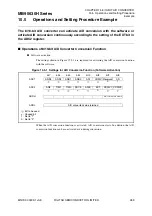
Below is an example of procedure for setting the 8/10-bit A/D converter:
●
Initial settings
1. Set the input port. (DDR)
2. Set the interrupt level. (ILR*)
3. Select an A/D input pin. (ADC1:ANS[3:0])
4. Set the sampling time. (ADC2:TIM[1:0])
5. Select the clock. (ADC2:CKDIV[1:0])
6. Set A/D conversion precision. (ADC2:AD8)
7. Select the operating mode. (ADC2:EXT)
8. Select the start trigger. (ADC2:ADCK)
9. Enable interrupts. (ADC2:ADIE = 1)
10. Activate the A/D conversion function. (ADC1:AD = 1)
*: For details of the interrupt level setting register (ILR), refer to "CHAPTER 5 INTERRUPTS" in this
hardware manual and "
■
INTERRUPT SOURCE TABLE" in the device data sheet.
●
Interrupt processing
1. Clear the interrupt request flag to "0". (ADC1:ADI = 0)
2. Read converted values. (ADDH, ADDL)
3. Activate the A/D conversion function. (ADC1:AD = 1)


