MB95630H Series
300
FUJITSU SEMICONDUCTOR LIMITED
MN702-00009-1v0-E
CHAPTER 17 CLOCK SUPERVISOR COUNTER
17.4 Registers
17.4.2
Clock Monitoring Control Register (CMCR)
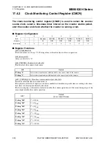
The clock monitoring control register (CMCR) is used to select the counter
source clock, select a time-base timer interval as the counter enable period,
start the counter and check whether the counter is running or not.
■
Register Configuration
■
Register Functions
[bit7:6] Undefined bits
Their read values are always "0". Writing values to these bits has no effect on operation.
[bit5] Reserved bit
Always set this bit to "0".
[bit4] CMCSEL: Counter clock select bit
This bit selects the counter clock source.
[bit3:1] TBTSEL[2:0]: Time-base timer counter output select bits
These bits select the time-base timer interval.
The operation of the clock supervisor counter is enabled and disabled at specific times according to the time-
base timer counter output selected by these bits.
The first rising edge of the interval selected enables the counter operation and the second rising edge of the
same output disables the counter operation.
bit
7
6
5
4
3
2
1
0
Field
—
—
Reserved
CMCSEL
TBTSEL2
TBTSEL1
TBTSEL0
CMCEN
Attribute
—
—
W
R/W
R/W
R/W
R/W
R/W
Initial value
0
0
0
0
0
0
0
0
bit4
Details
Writing "0"
Selects the external main oscillation clock as the source clock of the counter.
Writing "1"
Selects the external sub-oscillation clock as the source clock of the counter.
bit3:1
Details
(F
CRH
: main CR clock)
Writing "000"
2
3
×
1/F
CRH
Writing "001"
2
5
×
1/F
CRH
Writing "010"
2
7
×
1/F
CRH
Writing "011"
2
9
×
1/F
CRH
Writing "100"
2
11
×
1/F
CRH
Writing "101"
2
13
×
1/F
CRH
Writing "110"
2
15
×
1/F
CRH
Writing "111"
2
17
×
1/F
CRH

