MB95630H Series
464
FUJITSU SEMICONDUCTOR LIMITED
MN702-00009-1v0-E
CHAPTER 22 UART/SIO
22.6 Operations and Setting Procedure Example
The baud rate in clock asynchronous mode (UART) can be set in the following range.
●
Transfer data format
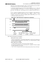
UART can treat data only in NRZ (Non-Return-to-Zero) format. Figure 22.6-2 shows the data
format.
The character bit length can be selected from among 5 to 8 bits depending on the settings of
SMC1n:CBL[1:0].
The stop bit length can be set to 1 or 2 bits depending on the setting of SMC1n:SBL.
The PEN bit and TDP bit in the SMC1n register can be used to enable/disable parity and to
select parity polarity.
As shown in Figure 22.6-2, the transfer data always starts from the start bit ("L" level) and ends
with the stop bit ("H" level) by performing the specified data bit length transfer with MSB first
or LSB first ("LSB first" or "MSB first" can be selected by the BDS bit in the SMC1n register).
It becomes "H" level at the idle state.
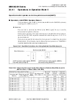
Figure 22.6-2 Transfer Data Format
Table 22.6-3 Baud Rate Setting Range in Clock Asynchronous Mode (UART)
PSS[1:0]
BRS[7:0]
0b00 to 0b11
0x02 (2) to 0xFF (255)
S
T
D0
D1
D2
D
3
D4
S
P
S
T
D0
D1
D2
D
3
D4
P
S
P
S
T
D0
D1
D2
D
3
D4
S
P
S
P
S
T
D0
D1
D2
D
3
D4
P
S
P
S
P
S
T
D0
D1
D2
D
3
D4
D5
D6
D7
S
P
S
T
D0
D1
D2
D
3
D4
D5
D6
P
S
P
D7
S
T
D0
D1
D2
D
3
D4
D5
D6
D7
S
P
S
P
S
T
D0
D1
D2
D
3
D4
D5
D6
P
S
P
D7
S
P
Witho
u
t P
With P
Witho
u
t P
With P
5-
b
it d
a
t
a
8
-
b
it d
a
t
a
S
T
S
P
P
:
S
t
a
rt
b
it
:
S
top
b
it
: P
a
rity
b
it
D0 to D7: D
a
t
a
. The
s
e
qu
ence c
a
n
b
e
s
elected from "L
S
B fir
s
t" or "M
S
B fir
s
t"
b
y the
direction control regi
s
ter (BD
S
b
it)
Note: 6-
b
it d
a
t
a
a
nd 7-
b
it d
a
t
a
h
a
ve the
sa
me d
a
t
a
form
a
t
as
5-
b
it d
a
t
a
.


