MB95630H Series
198
FUJITSU SEMICONDUCTOR LIMITED
MN702-00009-1v0-E
CHAPTER 14 LIN-UART
14.1 Overview
14.1
Overview
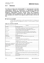
The LIN (Local Interconnect Network)-UART is a general-purpose serial data
communication interface for synchronous or asynchronous (start-stop
synchronization) communication with external devices. In addition to a bi-
directional communication function (normal mode) and master/slave
communication function (multiprocessor mode: supports both master and
slave operation), the LIN-UART also supports special functions with the LIN
bus.
■
Functions of LIN-UART
The LIN-UART is a general-purpose serial data communication interface for exchanging serial
data with other CPUs and peripheral devices. Table 14.1-1 lists the functions of the LIN-
UART.
Table 14.1-1 Functions of LIN-UART
Function
Data buffer
Full-duplex double-buffer
Serial input
The LIN-UART oversamples received data for five times to determine the received
value by majority of sampling values (only asynchronous mode).
Transfer mode
• Clock-synchronous (Select start/stop synchronization, or start/stop bits)
• Clock-asynchronous (Start/stop bits available)
Baud rate
• Dedicated baud rate generator provided (made of a 15-bit reload counter)
• The external clock can be inputted. It can be adjusted by the reload counter.
Data length
• 7 bits (not in synchronous or LIN mode)
• 8 bits
Signal type
NRZ (Non Return to Zero)
Start bit timing
Synchronization with the start bit falling edge in asynchronous mode.
Reception error detection
• Framing error
• Overrun error
• Parity error (Not supported in operating mode 1)
Interrupt request
• Receive interrupts (reception completed, reception error detected, LIN synch break
detected)
• Transmit interrupts (transmit data empty)
• Interrupt requests to TII0 (LIN synch field detected: LSYN)
Master/slave mode communication
function (Multiprocessor mode)
Capable of 1 (master) to n (slaves) communication
(supports both the master and slave system)
Synchronous mode
Transmit side/receive side of serial clock
Pin access
Serial I/O pin states can be read directly.
LIN bus option
• Master device operation
• Slave device operation
• LIN synch break detection
• LIN synch break generation
• Detection of LIN synch field start/stop edges connected to the 8/16-bit composite
timer
Synchronous serial clock
Continuous output to the SCK pin enabled for synchronous communication using the
start/stop bits
Clock delay option
Special synchronous clock mode for delaying the clock (used in Serial Peripheral
Interface (SPI))


