


7 - 32
C156-E097-01EN
(4)
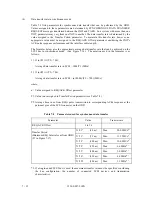
Data transfer rate in synchronous mode
Table 7.8 lists parameters for synchronous data transfer that can be performed by the ODD.
Values assigned to these parameters are determined by SYNCHRONOUS DATA TRANSFER
REQUEST messages transferred between the INIT and TARG. In a system with more than one
INIT, parameters may vary from one INIT to another. The data transfer rate is determined by the
value assigned to the Transfer Period parameter. To maintain this transfer rate, however, an
appropriate value must be assigned to the REQ/ACK Offset parameter considering the INIT's
ACK pulse response performance and the interface cable length.
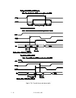
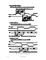
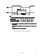
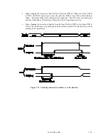
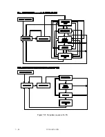
The formulas below give the approximate average data transfer rate that can be achieved on the
SCSI bus in synchronous mode. (See Figure 7.14.) The notation used in the formulas is as
follows:
1) If (n
×
T1)
≥
(T2 + 700),
Average data transfer rate in SCSI = 1000/T1 (MB/s)
2) If (n
×
T1)
>
(T2 + 700),
Average data transfer rate in SCSI = (n
×
1000)/(T2 + 700) (MB/s)
where,
n: Value assigned to REQ/ACK Offset parameter
T1: Value in ns assigned to Transfer Period parameter (see Table 7.8)
T2: Average time in ns from REQi pulse transmission to corresponding ACKi response at the
pertinent pins of the SCSI connector on the ODD
Table 7.8
Parameters used for synchronous data transfer
Parameter
Value
Transter rate
REQ/ACK Offset
1 to 16
X '0C'
(50 ns)
Max.
20.0 MB/s*
1
X '12'
(75 ns)
Max.
13.3 MB/s*
1
X '19'
(100 ns)
Max.
10.0 MB/s*
1
X '25'
(150 ns)
Max.
6.6 MB/s*
1
X '32'
(200 ns)
Max.
5.0 MB/s*
1
X '3E'
(250 ns)
Max.
4.0 MB/s*
1
X '4B'
(300 ns)
Max.
3.3 MB/s*
1
*1. If a single-ended SCSI bus is used, the maximum transfer rate must be specified considering
the bus configuration, the number of connected SCSI devices, and transmission
characteristics.
Transfer Period
(Minimum REQ Interval sent from ODD)
(T1 in Figure 7.17)
Summary of Contents for MCE3064SS
Page 1: ...C156 E097 01EN MCE3064SS MCF3064SS OPTICAL DISK DRIVES PRODUCT MANUAL ...
Page 3: ...This page is intentionally left blank ...
Page 31: ...This page is intentionally left blank ...
Page 52: ...C156 E097 01EN 2 21 Figure 2 3 Example of alternate processing ...
Page 53: ...This page is intentionally left blank ...
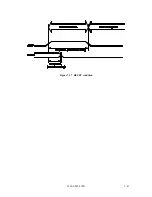
Page 72: ...C156 E097 01EN 3 19 Figure 3 17 SCSI cable connector ...
Page 81: ...This page is intentionally left blank ...
Page 97: ...4 16 C156 E097 01EN Figure 4 5 SCSI connection check 2 ...
Page 99: ...This page is intentionally left blank ...
Page 113: ...This page is intentinally left blank ...
Page 119: ...7 2 C156 E097 01EN Host system A Host system B Figure 7 1 Example of SCSI configuration ...
Page 133: ...7 16 C156 E097 01EN Figure 7 6 ARBITRATION phase ...
Page 135: ...7 18 C156 E097 01EN µ Figure 7 7 SELECTION phase 30 30 30 30 ...
Page 141: ...7 24 C156 E097 01EN Figure 7 10 Transfer in asynchronous mode 18 18 ...
Page 145: ...7 28 C156 E097 01EN Figure 7 11 Transfer in synchronous mode 11 11 11 11 43 18 43 18 ...
Page 146: ...C156 E097 01EN 7 29 Figure 7 12 Transfer in FAST SCSI mode ...
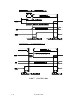
Page 148: ...C156 E097 01EN 7 31 Figure 7 13 Data transfer rate in asynchronous mode ...
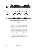
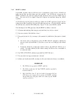
Page 158: ...C156 E097 01EN 7 41 Figure 7 17 RESET condition ...
Page 160: ...C156 E097 01EN 7 43 Figure 7 18 Bus phase sequence 1 of 2 ...
Page 161: ...7 44 C156 E097 01EN Figure 7 18 Bus phase sequence 2 of 2 ...
Page 167: ...This page is intentionally left blank ...
Page 171: ...This page is intentionally left blank ...
Page 181: ......


